Design of Microwave Radar for Human Attitude Detection
XIA Yanchao, WANG Yan*, GUO Ling
(School of Electrical Engineering, University of South China, Hengyang, Hunan 421001, China)
Abstract:In order to diversify and intelligentize application scenarios of microwave radar, a doppler microwave radar which can greatly reduce complexity of algorithm and realize basic human attitude detection function is designed, It combines microwave radar with attitude detection function. The microwave radar mainly includes sector beam antenna, integrated microstrip mixing circuit, body signal detection circuits, logical realization of attitude detection function and so on. Circuits is simulated and optimized by High Frequency Structure Simulator、Advanced Design System and Multisim respectively. Finally, after system integration test, it can be known that the system can output moving signal in the range of 15~40 Hz, the tiny-action signal in the range of 1~7 Hz and the breathing signal in the range of 250~500 mHz by operating frequency of 5.8 GHz and they can be detected by MCU. These signals can be used for human behavior prediction at smart home system and intelligent medical field for detection of patients’ heartbeat and respiration.
Keywords:sector beam; mixing circuit; tiny signal detection; attitude detection
0 Introduction
Doppler radar is a type of microwave radar that works based on the Doppler effect by detecting the echo signals radiated into space and reflected back by target objects. The echo signals contain rich information about the target, such as existence, distance from the radar, angle, etc. With the improvement of software algorithm technology, it can also identify more precise and complex information related to the target[1].
Attitude detection was initially an important research direction in the field of artificial intelligence, but with the in-depth research of related technologies, research results related to attitude detection technology have begun to be promoted to other industries and gradually transformed into tangible applications. Attitude detection technology is widely used in fields such as intelligent monitoring, natural human-computer interaction, virtual reality sports training, medical rehabilitation exercises, and intelligent monitoring, and it also shows great application potential in emerging consumer fields such as fitness and motion-sensing games, with broad application prospects[2].
The main working process of conventional microwave radars with attitude detection function is: after the radar sensor detects the echo signal, it first preprocesses it, converting the one-dimensional signal into a two-dimensional signal, maximizing the extraction of attitude characteristics while filtering out other interference signals. Then, based on the results of preprocessing, relevant algorithms are used for recognition and classification, compared with the corresponding database, and finally the function of attitude detection is completed. The whole process involves a large amount of data processing and has high requirements for the quality and quantity of training samples, which undoubtedly increases the R&D costs of the entire product[3].
This paper will design a Doppler microwave radar that can perform basic human attitude detection functions. Through reasonable design of the hardware circuit, it can greatly reduce the complexity of software algorithms. This product can be used in the fields of smart homes and intelligent healthcare. In the smart home field, it can predict behaviors by detecting basic postures such as lying, sitting, and standing, to activate related electronic smart devices; in the medical field, it can be used to continuously monitor the breathing and heartbeat of patients in bed, ensuring that medical staff can respond promptly to emergencies; at the same time, it also has broad development prospects in daily lighting applications. The entire system circuit mainly consists of a sector beam antenna, integrated mixing reception circuit, body signal detection circuit, and other components.
1 Sector Beam Antenna
Due to limitations of dielectric substrate and the shape of radiation patches, the gain of a single traditional microstrip antenna is generally between 6 dB and 8 dB. To achieve specific directionality and high gain, multiple array antennas are often needed in engineering. In this paper, to achieve the attitude detection function, the working antenna needs to radiate a sector-like detection beam. To achieve this purpose, several microstrip radiation patches can be combined to form a microstrip linear array antenna.
When designing the array antenna, the element antenna must first be designed. When the microstrip antenna operates, the space above the radiation patch is free space, and the space below is the dielectric substrate. The antenna does not exist in a uniform medium. Therefore, to simplify calculations, the effective dielectric constant εe is often introduced to analyze the antenna, which is equivalent to the microstrip antenna being in a uniform medium with a dielectric constant of εe. Given the relative dielectric constant of the medium εr, the expression for εe is:
 (1)
(1)
In formula (1), w is the width of the rectangular patch, and the expression is:
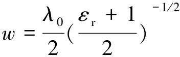 (2)
(2)
In formula (2), λ0 is the electromagnetic wavelength in vacuum, and according to empirical formulas, the length of the rectangular microstrip patch is
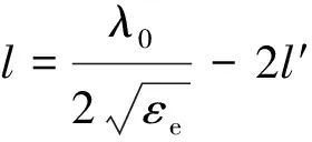 (3)
(3)
In formula (3), l′ is the correction factor, and the expression is
 (4)
(4)
Knowing that the relative dielectric constant of Rogers RT/duroid 4003 is 3.55, when used as dielectric substrate material, the theoretical initial size of the microstrip antenna for maximum radiation efficiency is W0=16.5 mm and L0=13.0 mm, which is used to design the array antenna[4-6].
Research shows that when the current paths of the rectangular microstrip antenna are different in various directions to a certain extent, the radiation characteristics of the antenna will change. This paper adopts an improved arc structure for the antenna element, reducing the area of the radiation patch, increasing the current signal path, and enhancing the coupling effect between the antenna and the reference ground, thereby altering the radiation characteristics of the antenna. The final array antenna is shown in Figure 1.
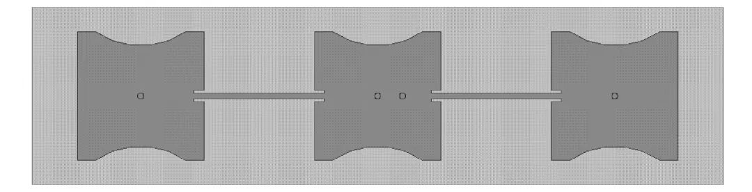
Figure 1 Sector Beam Antenna
The entire array antenna adopts coaxial series feeding. For odd-numbered elements, this method can significantly reduce the size of the antenna. Impedance matching between the elements on both sides is achieved through insertion, allowing for flexible adjustment of the antenna’s impedance. By adjusting the overall size parameters of the antenna, the input impedance of the antenna can be matched with the feeding port. Through three-dimensional electromagnetic simulation software High Frequency Structure Simulator (HFSS), multiple simulations and optimizations of the antenna were conducted, resulting in the optimal size parameters of the antenna: the spacing between elements d≈24 mm, and the overall size of the antenna is 24 mm×70 mm×1.07 mm. The simulated gain of the antenna is shown in Figures 2 and 3.
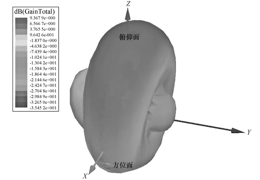
Figure 2 Three-Dimensional Gain of Antenna
From the three-dimensional gain plot of the antenna in Figure 2, it can be seen that the overall radiation characteristics of the antenna are similar to a sector shape, with a gain of 9.4 dB. At the same time, there are certain horizontal side lobes on both sides, but since the number of elements is relatively small, the effect of the smaller side lobes can be ignored. From the two-dimensional gain plot of the antenna in Figure 3, it can be observed that the half-power beam width (HPBW) of the E-plane and H-plane are 105° and 31° respectively, indicating that the radiation characteristics have significantly changed compared to commonly used detection antennas, with a substantial increase in the HPBW of the E-plane and a significant decrease in the HPBW of the H-plane.
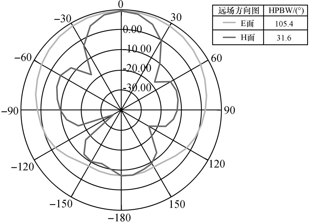
Figure 3 Two-Dimensional Gain of Antenna
The voltage standing wave ratio (VSWR) indicates the ratio of the voltage amplitude at the antinode of the standing wave to that at the node, which is an important parameter for measuring the loss of the antenna during operation. After HFSS simulation optimization, the VSWR curve of the input port of the array antenna is shown in Figure 4. The comparison curve of the VSWR for element antenna and array antenna in the range of 5.5 GHz to 6.3 GHz is shown in Figure 5. From Figures 4 and 5, it can be seen that at 5.8 GHz, the VSWR value of the input port of the array antenna is closer to the ideal state of 1 compared to the element antenna. The simulation results of the antenna prove the rationality of the sector beam antenna design and that it can meet engineering requirements well.
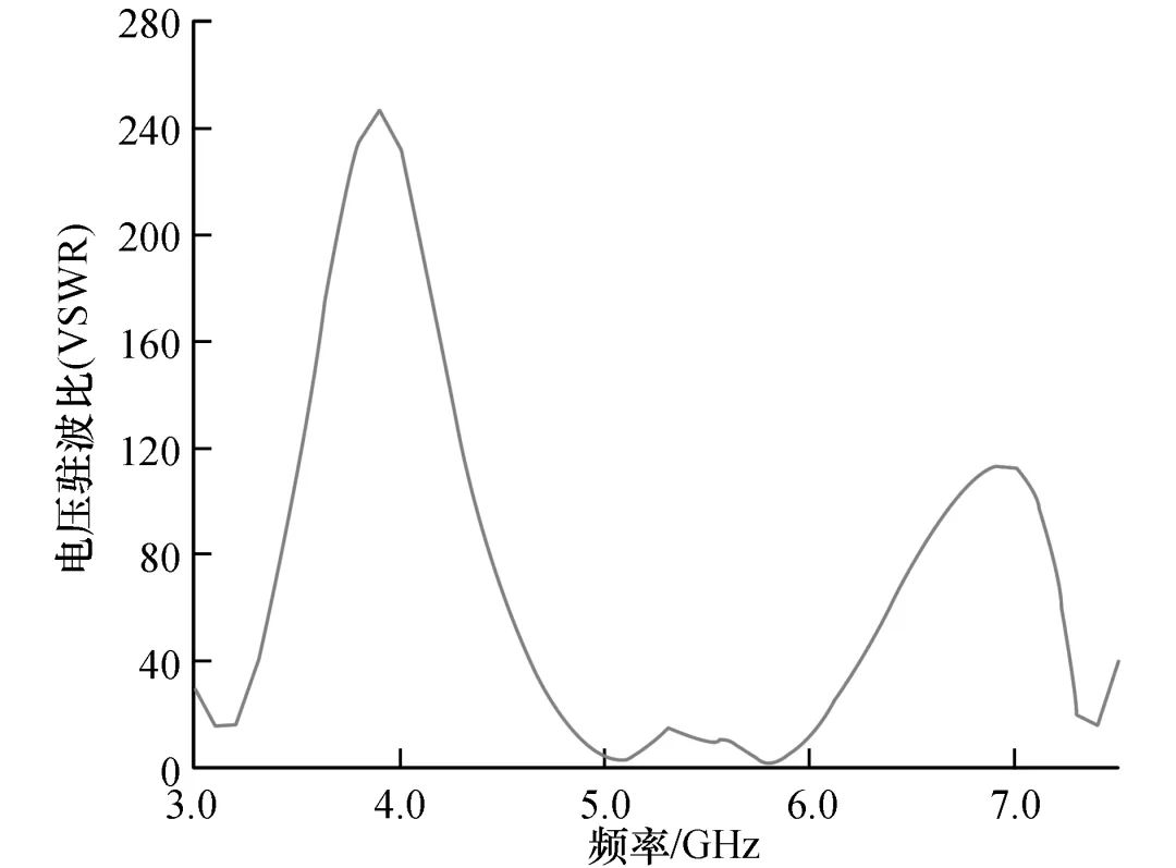
Figure 4 VSWR of Input-Port for Antenna
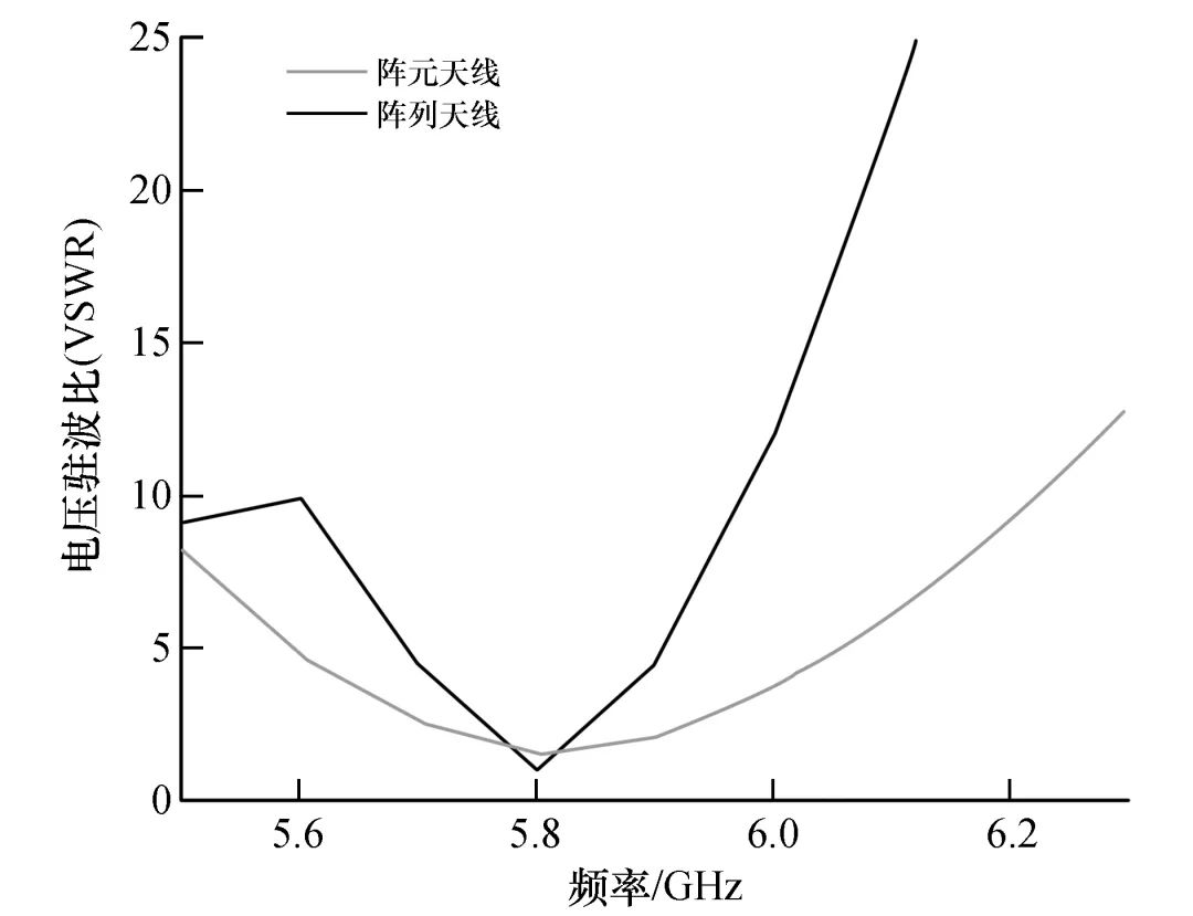
Figure 5 VSWR of Element Antenna and Array Antenna
2 Mixing Circuit Design
The mixer is generally regarded as a three-port device, with two signal input ports and one signal output port. The core of the mixing circuit is a nonlinear device, where two input signals of different frequencies will generate a series of new signals with frequencies different from the input signals after passing through the nonlinear device. After filtering, the required frequency signal can be obtained[7-8].
This paper designs an integrated mixing circuit that has functions for transmitting, receiving, filtering, mixing, and input-output impedance matching, effectively reducing the area of the microstrip circuit while ensuring basic receiving functions. The mixing circuit uses a Schottky barrier diode as the mixing device, structured as a microstrip balanced mixing circuit. After establishing the model with parameters of the Schottky barrier diode during operation, the schematic and Momentum circuit are jointly simulated using RF circuit design software Advanced Design System (ADS), as shown in Figure 6, with the main parameters after simulation shown in Figure 7.
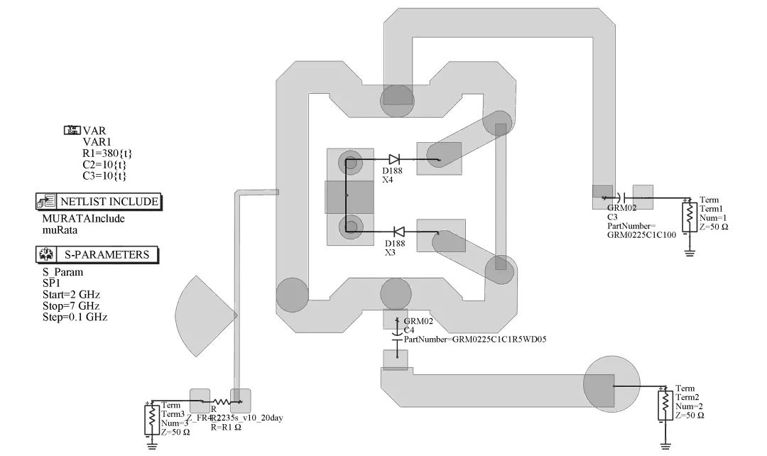
Figure 6 Structure of Mixer Circuit
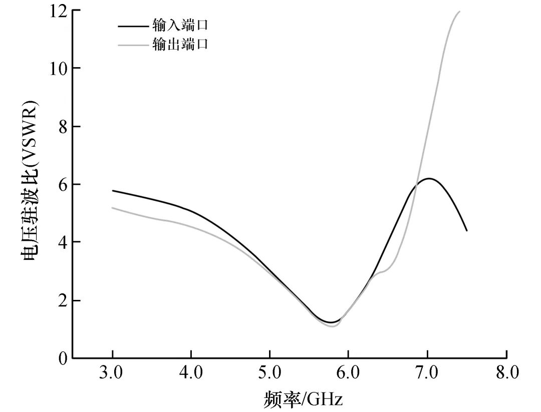
Figure 7 VSWR of Input and Output Ports
From Figure 7, it can be seen that the voltage VSWR at the input and output ports at 5.8 GHz are 1.2 and 1.1, respectively, very close to 1. This indicates that the impedance matching of the input-output of the designed mixing circuit structure is good, and microwave signals can significantly reduce dielectric losses during transmission through the mixing circuit, thereby further enhancing the peak value of the intermediate frequency signal after mixing.
3 Body Signal Detection Circuit
Body signals are signals emitted by the human body that contain specific information in daily life. Common body signals include motion signals, EEG signals, ECG signals, and respiration/heartbeat signals. Many body signals fall into the category of tiny signals in circuit systems, with signal voltage amplitudes generally ranging from tens of microvolts to several millivolts. If these signals are not processed through amplification, filtering, and other stages, it is difficult to recognize and utilize them. Although there are some highly precise instruments available domestically and internationally that can directly detect, analyze, and utilize these signals, they are relatively expensive. Therefore, it is necessary to adopt a more universally applicable and cost-effective tiny signal detection circuit[9].
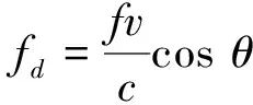
The body signal detection circuit in this paper mainly targets the detection of human moving signals, tiny action (micro-motion) signals, and breathing signals. The main theoretical basis for circuit design is the Doppler effect; according to the Doppler frequency shift formula, for a fixed wave source in Doppler microwave radar, the relationship between the frequency of the detected moving object and the frequency of the emission source is:
 (5)
(5)
In formula (5), fd is the frequency of the Doppler shift, in Hz; f is the frequency of the wave source, in Hz; c is the speed of electromagnetic waves in the medium, in m/s; when the medium is air, c is the speed of light; v is the speed of the detected object, in m/s; θ is the angle between the detected object and the wave source, in degrees (°). Based on the Doppler frequency shift formula, the corresponding frequency range of human signals at the working frequency can be calculated, and the corresponding filtering and amplification circuit can be designed[10].
When the working frequency of the wave source is 5.8 GHz, the conventional human moving signal after mixing is in the range of 15~40 Hz, the micro-motion signal is in the range of 1~7 Hz, and the breathing signal is in the range of 250~500 mHz. It is noteworthy that the amplitude of the mixed output signal is particularly low; without amplification circuit processing, it cannot be detected by commonly used MCUs for practical applications.
Among the three types of body signals mentioned above, the voltage amplitude of the moving signal is the largest, followed by the micro-motion signal, and the breathing signal has the smallest voltage amplitude. Based on these considerations, in addition to limiting the bandwidth of the signal detection circuit, it is also necessary to consider the overall amplification gain of the circuit. The body signal detection circuit was designed using circuit simulation software Multisim, as shown in Figures 8, 9, and 10.
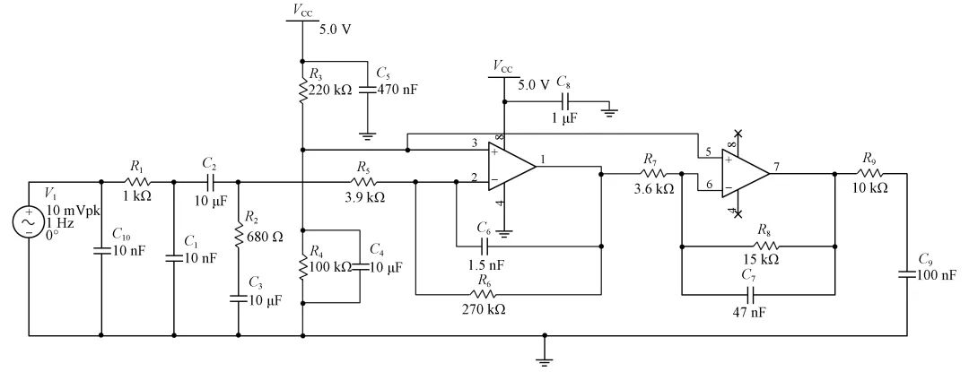
Figure 8 Circuit of Moving Signal Detection
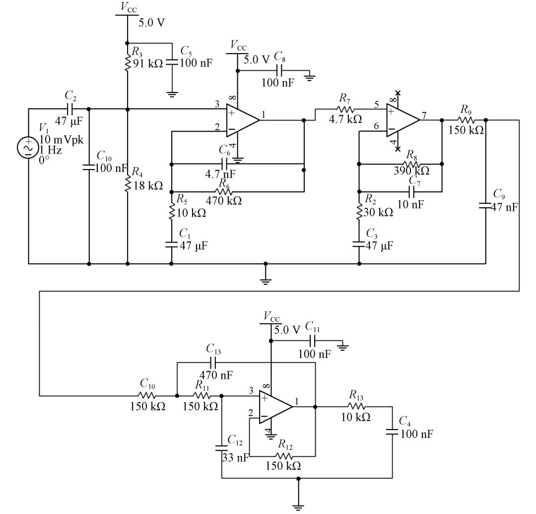
Figure 9 Circuit of Tiny Action Signal Detection
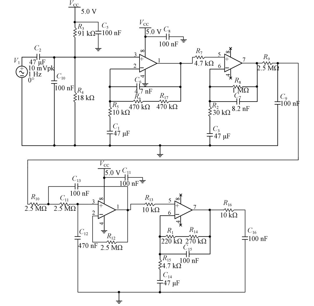
Figure 10 Circuit of Respiratory Signal Detection
After performing frequency sweep simulation analysis on the body signal detection circuit, it can be concluded that the maximum gains within the bandwidth of each circuit are 57 dB, 60 dB, and 80 dB, respectively. The signals within the corresponding target frequency bands will be well amplified, while signals outside the target frequency bands will be significantly attenuated.
To better verify the overall performance of the signal circuit, the various signal circuits were integrated onto a single circuit board and subjected to system testing, as shown in Figure 11.
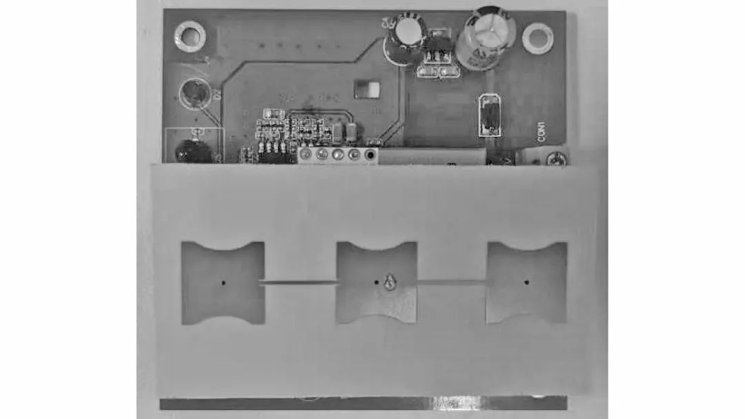
Figure 11 Integration Test
In daily life, the signals of human activities are random. Therefore, to facilitate the verification of the circuit’s functionality, the output signals of each detection circuit were observed using an oscilloscope, capturing a complete waveform for observation, with results shown in Figures 12, 13, and 14.
From Figures 12, 13, and 14, it can be observed that the frequency of the moving signal is 32 Hz, the frequency of the micro-motion signal is 3 Hz, and the frequency of the breathing signal is 300 mHz. Thus, it can be concluded that the final output signal frequencies fall within their respective frequency ranges, and the signal amplitudes are sufficiently high to be sampled and detected by the MCU.
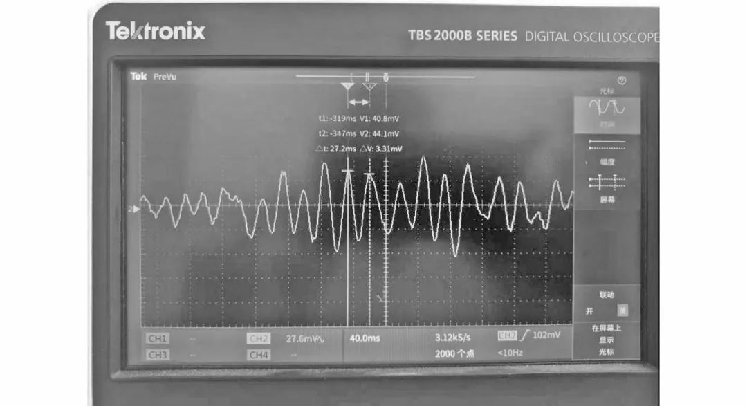
Figure 12 Output Waveform Signal of Moving Signal
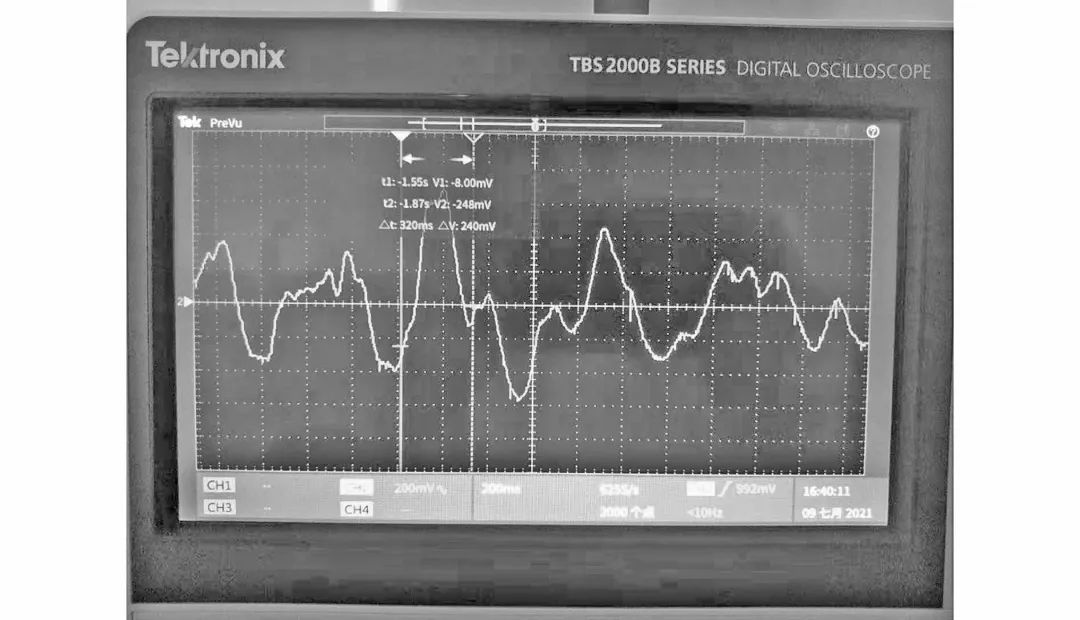
Figure 13 Output Waveform Signal of Micro-motion Signal
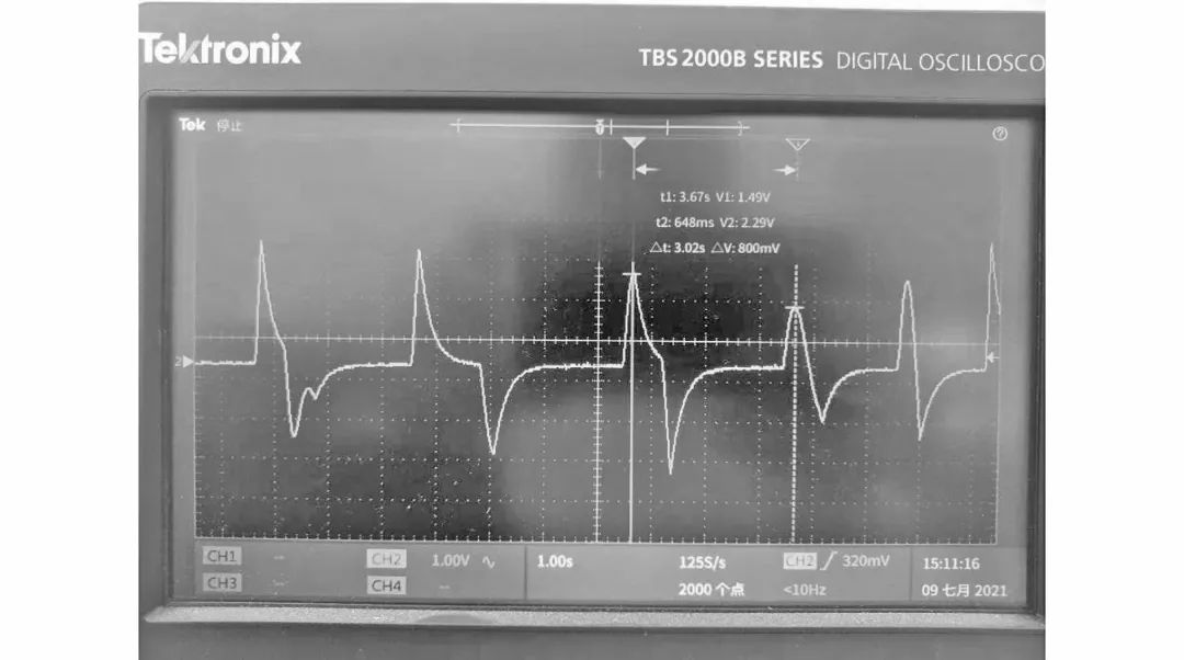
Figure 14 Output Waveform Signal of Breathing Signal
It should be noted that there are significant differences in the signals emitted by the human body under two different conditions: during movement and while remaining still. The body signal detection circuit designed in this paper is only suitable for detecting human signals in daily life without the premise of vigorous exercise. The body signals output by the signal detection circuit can achieve basic attitude detection functions through simple frequency and amplitude recognition via software.
4 Logical Implementation of Attitude Detection Function
The Doppler microwave radar designed in this paper is essentially a time-shifted microwave detection device. In an indoor environment, this time-shifted microwave detection device can emit multiple sector-shaped detection beams that are time-shifted, and at any given moment, only one corresponding radiation element is operational, thereby forming a time-shifted partitioned scanning detection for the corresponding area based on the directionality of the detection beams, as shown in Figure 15.
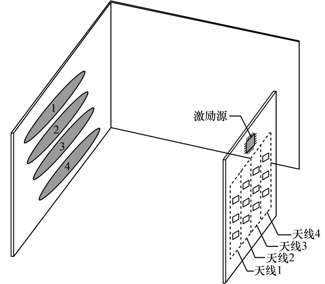
Figure 15 Detection Beam of Radar
In the application of basic human attitude detection, the microwave radar is installed on the wall, and the corresponding detection space is scanned in layers and time-shifted through the sector beam antenna. When radiation antennas 1, 2, 3, and 4 in Figure 15 detect human signals (Doppler signals) in areas 1, 2, 3, and 4, it can be determined that the human body is in a standing position in the indoor environment; if antennas 2, 3, and 4 detect human signals in areas 2, 3, and 4, while antenna 1 does not detect human signals in area 1, it can be determined that the human body is in a sitting position; if antenna 3 detects a human signal in area 3, while other antennas do not detect human signals in their respective areas, it can be determined that the human body is lying down in the indoor environment.
Furthermore, after determining that the human body is lying down in the indoor environment, the microwave sensor can change the duty cycle of the excitation signal working on radiation antenna 3 to switch to a breathing detection mode to detect the human’s sleep state. For example, whether the person is in a state of falling asleep, sound asleep, or awake, thereby controlling the working states of electronic devices such as lights and air conditioners in the indoor environment[11-12].
5 Conclusion
This paper combines microwave radar technology with attitude detection to design a microwave radar capable of detecting basic human attitudes indoors. Under a working frequency of 5.8 GHz, the microwave radar can detect corresponding human moving signals, tiny-action signals, and breathing signals within the detection area. It can be used for behavior prediction in smart home fields and for heartbeat and respiration detection of patients in the medical field.
The entire design includes microwave antennas, mixing circuits, signal detection circuits, and other components, with a simple structure and low manufacturing costs, which contributes to promoting the construction of smart homes and diversifying application scenarios of microwave radar. It broadens the ideas for the design of subsequent related microwave radar products and provides certain reference significance for the design of other related circuits.
References:
[1] VALLDECABRES L,VON BREMEN L,KÜN M.Minute-scale detection and probabilistic prediction of offshore wind turbine power ramps using dual-doppler radar[J].Wind energy,2020,23(12):2202-2224.
[2] HUA B,LIU R P,WU Y H,et al.Intelligent attitude planning algorithm based on the characteristics of low radar cross section characteristics of microsatellites under complex constraints[J].Proceedings of the institution of mechanical engineers,part G:Journal of aerospaceengineering,2019,233(1):4-21.
[3] 董尧尧,曲卫,邱磊.毫米波雷达手势识别综述[J].兵器装备工程学报,2021,42(8):119-125.
[4] 王辉,赵海明,王汝征,等.一种串馈微带阵列天线设计方法[J].制导与引信,2018,39(2):37-41.
[5] HASHIM Z,GOTRA S,PANI S,et al.Ku-bandmicrostrip patch linear array antenna for police radar system[J].Indian journal of science and technology,2017,10(30):1-4.
[6] SOOD K,JYOTI R,SHARMA S B.Linear array modules with prescribed excitations usingwaveguide shunt slot-fed microstrip patch elements[J].International journal of microwave and wireless technologies,2013,5(5):637-644.
[7] 吕昌林.超宽带微波混频器MMIC的研究与设计[D].西安:西安电子科技大学,2019:7-21.
[8] 陈伟民,李存龙.基于微波雷达的位移/距离测量技术[J].电子测量与仪器学报,2015,29(9):1251-1265.
[9] 赵庭兵,曾曾.光电检测系统的微弱信号采集与检测[J].激光杂志,2018,39(11):158-161.
[10] 覃贵礼,王显梅.光电检测系统的微弱信号检测研究[J].科技通报,2019,35(9):48-51;56.
[11] 元志安,周笑宇,刘心溥,等.基于RDSNet的毫米波雷达人体跌倒检测方法[J].雷达学报,2021,10(4):656-664.
[12] 张建宏,武锦辉,刘吉,等.基于FPGA的多普勒雷达测速系统[J].国外电子测量技术,2019,38(12):72-75.