2016 Microcomputer and Applications Issue 18
Authors: Shen Yi, Chen Zhangjin, Zhang Hongbin, Wu Zhiguo
Abstract: This paper proposes a design for a maintenance key based on Bluetooth Low Energy technology to address the issues faced by enterprises using traditional keys to manage key cabinets, such as centralized management and poor security. The system uses mobile terminals as intermediaries, allowing enterprises to manage maintenance keys in key cabinets across various parking lots through a cloud platform. When a key cabinet malfunctions, parking personnel can apply for emergency access to the key cabinet through the platform and use a special sensing chip to activate the system, then unlock the cabinet through a dedicated APP. This system offers good stability and security, effectively enhancing service response times and improving user satisfaction.
0 Introduction
With the rapid development of the economy, cities like Shanghai have entered a stage of rapid urban mobility, where the growth of motor vehicle ownership and usage far exceeds that of parking facilities. The difficulty of finding parking in densely populated areas such as city centers and commercial districts severely affects citizens’ travel. In this environment, internet companies providing valet parking services have emerged, establishing online parking platforms where users hand over their vehicles and keys to dedicated parking attendants and contact them to retrieve their cars when needed.
Dedicated key cabinets are built in parking lots to correspond to the car keys of users. As the number of users has significantly increased, the high costs, risks, and complexities associated with manual storage and retrieval have restricted market development. The intelligent cloud key cabinet based on Bluetooth Low Energy (BLE) has emerged, allowing parking attendants to complete order receiving, key storage, and on-site confirmation through a dedicated APP. The key cabinet is equipped with a maintenance key to address malfunctions. To overcome the various issues associated with manually managing maintenance keys, this paper proposes a high-security and reliable maintenance key solution.
1 System Architecture Design
1.1 System Architecture
The system mainly consists of a cloud platform, mobile APP, and central control device, as shown in Figure 1.

This paper will focus on the design of the central control device, which has two working modes: maintenance mode and normal mode.
(1) Maintenance Mode: In this mode, the APP can set the private key of the encryption module of the central control device and store it encrypted in the cloud platform; it can accept APP modifications to BLE module parameters. The maintenance mode includes all functions of the normal mode.
(2) Normal Mode: Receives, identifies, authenticates, responds to, and executes the APP’s command to open the maintenance key cabinet. In normal mode, requests to reset the encryption key from the APP are not accepted to enhance system security.
The Generic Access Profile (GAP) of the BLE protocol defines device roles. The central control device acts as a Peripheral Device, while the APP acts as a Central Device. After powering on, the central control device sends broadcast signals waiting for the APP to search, connect, and transmit data. The working mode can be switched via a switch on the central control device.
1.2 Working Process
During the installation and maintenance phase, the APP requests the 32-bit index number and BLE module parameters corresponding to the target parking lot and key cabinet from the cloud platform via cellular mobile data network; after the central control device is powered on, it searches and connects, using a specific communication protocol to send the above information to the central control device; upon receiving the data communication, the central control device identifies the command type and executes and responds accordingly. After setting the encryption module, it will return a 128-bit current key. After the APP receives the key, it will send it back to the cloud platform after link encryption and specific data encryption processing, with the cloud platform responsible for decryption and persistence.
During normal operation, to slow down the aging of the central control device and enhance security, the central control device remains in sleep mode. When the Hall switch responds to a change in the magnetic field, the central control device powers on. If no valid command is received from the APP within a certain time, it will re-enter sleep mode. In normal mode, commands to modify keys and BLE parameters are still considered invalid commands. Upon receiving the unlock command, the data message is decrypted through the encryption and decryption module to determine if it meets specific rules, and based on the result, it executes the unlock or ignores it.
2 Hardware Design and Implementation
The central control device is centered around the 8051 architecture STC15W404S series microcontroller (MCU), which has a high-precision clock, a set of UARTs, and three 16-bit general-purpose timers. Its low power consumption, high performance, and strong anti-interference capabilities meet the design requirements.
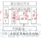
The circuit of the central control device includes BLE communication circuit, Hall effect switch circuit, power divider circuit, encryption chip circuit, and unlock driver circuit, as shown in the overall hardware circuit block diagram in Figure 2.
2.1 BLE Communication Circuit
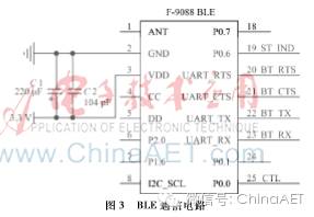
The BLE communication circuit mainly consists of the CC2541 and peripheral circuits. It can flexibly configure device parameters such as transmission power, broadcast interval, connection interval, module name, etc., to establish a key cabinet maintenance network. The low-energy protocol stack (BLE-STACK) provided by TI supports the complete protocol content, where the Logical Link Control and Adaptation Profile (L2CAP) supports a Maximum Transmission Unit (MTU) of 23 B. The CC2541 chip has two built-in USARTs that can be configured for UART or SPI mode. To enhance the modularity of the central control device and reduce system coupling, the design in this paper uses the BLE module F-9088. This module supports bidirectional 20 B data transmission for Android and iOS mobile operating systems. It is powered by a 3.3 V power supply and connects to the MCU for data exchange via the UART interface. The principle is shown in Figure 3.
2.2 Hall Effect Switch Circuit
The maintenance key, as one of the most important components of the key cabinet, requires high concealment, reliability, and security. The concealment requires that the interfaces of the central control device are not easily detectable; traditional mechanical switches cannot meet these requirements. The Hall effect switch proposed in this paper uses a strong magnet placed inside the central control device, which can be triggered by any object containing iron, cobalt, or nickel, regardless of its appearance. Reliability requires that the central control device can resist aging for a long time and restart according to actual needs. Security means that the central control device should have a certain ability to resist cracking attacks. During normal operation, when the Hall effect switch is not triggered, the APP cannot search for the key cabinet. Within a connection window, if a valid request cannot be sent, the system will re-enter power-off state, requiring the switch to be triggered again. This method can prevent certain degrees of brute force attacks.
The Hall sensing circuit uses the HW-300B linear Hall IC provided by AKEMD, which amplifies the signal through two stages of LM358 operational amplifiers. The principle is shown in Figure 4.
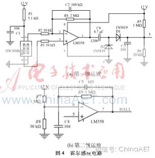
When the sensing chip triggers a change in the magnetic field, the HALL end generates a high level, causing the relay to engage, and then the voltage is divided to supply each module after dividing the 12 V.
2.3 Power Divider Circuit
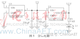
The working voltage of each module in the central control device varies; the unlock driver circuit operates at 12 V, the MCU operates at 5 V, and the BLE module and encryption chip operate at 3.3 V. At the same time, the MCU needs to have the function of controlling the relay to turn off its own power supply. The input voltage is 12 V, which is divided to 5 V through the 78L05 voltage regulator, and then divided to 3.3 V through the PJ6206-332MR voltage regulator. The principle is shown in Figure 5.
2.4 Encryption Chip Circuit
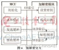
The ENTANG-A encryption chip from Neowine is used, supporting the aes-128-ecb algorithm for encryption and decryption. The chip provides a 400 kb/s I2C interface, and the MCU connects to the encryption chip via a general I/O port, using an analog I2C communication method. One clock cycle of the encryption chip is 250 ns, and one encryption or decryption operation requires 1,113 clock cycles, meeting the design requirements. The interaction between the MCU and the encryption chip is shown in Figure 6.
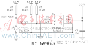
To prevent malicious tampering with the encryption chip key, this paper proposes switching the working mode via a dip switch to prompt the MCU to accept or reject key modification commands. The principle is shown in Figure 7.
3 Software Design
The cloud platform is responsible for storing keys and providing services to query keys by parking lot, number, etc. The APP interacts with the cloud platform via cellular mobile data. The BLE module establishes transparent data transmission between the MCU and the APP via UART.
3.1 Microcontroller Software Design
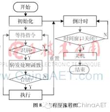
The MCU mainly completes functions such as command recognition, key setting, and unlocking. Upon powering on, the MCU initializes the internal components such as I/O ports, timers, and UART. It needs to immediately set the HOLD terminal (P3.4) high to maintain power supply. It starts a countdown, during which if no valid command is received, it sets the HOLD terminal low, turns off the power, and waits for the next power-on. After successfully verifying the unlock command, it maintains a high level on the unlock signal terminal for 0.3 s to unlock the lock. The main program flow is shown in Figure 8.
3.2 BLE Communication Data Transmission
During the data transmission process, the MCU uses an interrupt method for UART transmission and reception. The MTU supported by the BLE module is 20 B, and separate 20 B storage areas will be allocated to distinguish between sending and receiving. The transmission time for UART data of one MTU is:

Where rbaud is the UART baud rate; w is the number of bits in 1 B; lMTU is the number of bytes in one MTU. When rbaud is set to 57,600 b/s, the error rate is relatively low, at which point the time is approximately 2.8 ms.
To balance data throughput and energy consumption, the BLE communication connection interval is set to 100 ms. If the UART completes a data transmission of one MTU within this time, it does not affect BLE communication.
During data sending, data is loaded into the sending buffer, the RTS of the BLE module is set low, triggering the UART sending interrupt, and in the interrupt handler, each byte is placed into the UART sending register. After the last byte is transmitted, the RTS of the BLE module is set high.
When receiving data starts, in the interrupt handler, each byte is loaded into the receiving buffer, and the CTS of the BLE module is checked to see if it is set high to indicate that a data reception is complete. After data reception is complete, a semaphore is sent to the MCU main program to start the command recognition task.
3.3 Encryption and Decryption Software Design
The encryption module provides key settings, encryption and decryption mode selection, encryption, decryption, and testing functions via the I2C protocol.
When the MCU receives a key setting command, it first checks the level of the KEY_GEN (P3.2) pin to determine whether the central control device is currently in maintenance mode, and based on the result, it either rejects or executes the command. When setting the key, it sends 4 B of initialization parameters for generating the encryption chip key and finally reads the current 16 B key from the encryption chip register.
When the MCU receives an unlock command, it extracts the 16 B message from the command according to the interaction protocol, verifies it after decryption, and based on the result, it either rejects or executes the command. It first sets the encryption chip working mode to decryption mode, sends the 16 B ciphertext, and after one decryption cycle, reads the 16 B plaintext from the register.
4 Conclusion
The maintenance key designed based on Bluetooth Low Energy technology meets the requirements for long standby and anti-aging, with strong concealment, reliability, and security, as well as the ability to resist brute force cracking, allowing enterprises to reduce maintenance personnel costs and enhance service response speed in the application of cloud intelligent key cabinets. In actual use, the signal is stable within a range of 1 m from the key cabinet, and the system response speed is fast. An upgrade port has been reserved to meet the periodic upgrade of the interaction protocol to further enhance system security.
References
[1] Implementation opinions on promoting the informationization of the parking industry in Shanghai (Hu Jiao Huo [2014] No. 72) [R]. Shanghai: Shanghai Municipal Transportation and Port Bureau, Shanghai Municipal Development and Reform Commission, Shanghai Municipal Economic and Information Technology Commission, 2014.
[2] Bluetooth SIG. Bluetooth specification V4.0 [EB/OL]. (2010 06 30) [2016 04 20] https://www.bluetooth.org/docman/handlers/downloaddoc.ashx?doc_id=229737.
[3] Peng Yehui. Design of CMOS High-Precision Hall Switch Circuit [D]. Shanghai: Shanghai Jiao Tong University, 2014.
[4] National Institute of Standards and Technology (NIST). Federal information processing standards PUBS 127 [EB/OL]. (2001 11 26) [2016 04 20] http://csrc.nist.gov/publications/fips/fips197/fips-197.pdf.
[5] Texas Instruments Inc. CC253x/4x user’s guide (Rev.F) [EB/OL]. (2014 04 09) [2016 04 20] http://www.ti.com/litv/pdf/swru191f.