
Author: Yoshihide Goto, Akihisa Kumaki, Takashi Nakano | Anritsu
1. Introduction
Bluetooth technology is widely used in short-range wireless devices such as headphones, speakers, smartwatches, etc. Since the first standard was established in 1998, the application range of Bluetooth has continuously expanded, not only including data transmission but also developing applications such as distance detection and direction finding.
Currently, the application of Bluetooth technology has become more extensive, and a large ecosystem has developed around connection testing and certification testing to ensure excellent interconnectivity between Bluetooth devices. Anritsu became a member of the Bluetooth SIG in 1999 and has since actively participated in the introduction of new standards and interconnect testing. The MT8852B Bluetooth tester (hereinafter referred to as MT8852B) was developed based on the experience gained from these activities and is an indispensable tool in the RF test environment to ensure Bluetooth hardware performance, which can be used for evaluating products under development as well as in production manufacturing.
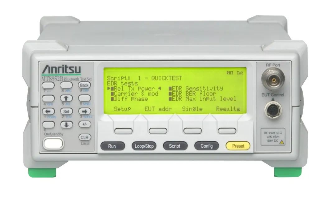
The MT8852B has the capability to control Bluetooth devices in RF testing, making it an ideal choice for configuring independent measurement environments. The second part of this article will focus on its new features in Bluetooth direction finding.
2. Evolution of Bluetooth Low Energy
The first Bluetooth standard covered basic rates (BR) for devices such as phone headsets, with a rate of 1 Mbps, which was later extended to Enhanced Data Rate (EDR) to support faster data rates (2 and 3 Mbps) to meet the needs of applications requiring higher rates, such as music streaming. The Bluetooth Low Energy (BLE) standard was subsequently released to reduce power consumption and extend battery life, unlike wireless systems such as mobile phones and wireless LANs, which aim for higher rates.
2.1 What is Bluetooth Low Energy
Compared to the BR and EDR specifications, the Bluetooth Low Energy specification is simplified, designed to reduce power consumption by adopting a configuration that flexibly controls communication timing. Therefore, remote devices such as temperature sensors can operate for years on a small button battery. Additionally, it supports the aggregation of mesh networks by increasing the number of simultaneously connected devices.
2.2 Advantages of Bluetooth Low Energy at the Physical Layer
The Bluetooth Low Energy physical layer standard uses the same GFSK modulation method as the basic rate, with the primary goal of extending physical layer-related functionalities while minimizing hardware modifications. Table 1 lists some of the Bluetooth Low Energy physical layer specifications and features.
Table 1 Physical Layer Features of Bluetooth Standards
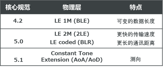
Different low-energy standards have different physical layer packet formats, as shown in Figure 1.
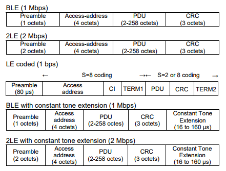
Figure 1 Low Energy Physical Layer Packet Format
The 2LE standard increases the transmission rate from 1 Mbps to 2 Mbps while maintaining the BLE packet format, excluding the Preamble. However, the number of bits in the Preamble length is doubled to 2 octets to ensure the type of the physical layer is detected as the time length is the same.
The LE standard encodes data to double or eight times the length (excluding the Preamble) to achieve coding gain for longer distance transmission. Here, the Preamble is ten times longer than that under BLE to ensure synchronization can be maintained even at low power.
Direction Finding adds a continuous signal called Constant Tone Extension at the end of normal BLE and 2LE packets (by sending a modulated signal of continuous bits of 1 at +1 MHz relative to the carrier frequency) (as shown in Figure 2).
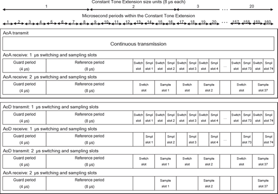
Figure 2 Constant Tone Extension (CTE) Structure
2.3 Direction Finding
Bluetooth direction finding is achieved through a combination of one antenna in the Tx or Rx antenna array and other single antennas. When sending (or receiving) Constant Tone Extension, time sharing will be used on one side of the antenna array. The antennas switch sequentially at constant time intervals (as shown in Figures 6 and 7).
The single antenna side only uses the traditional physical layer to send or receive signals, helping to reduce costs by using the original unmodified hardware. Additionally, direction finding can be achieved through multiple locations for indoor positioning technologies.
-
Direction Finding Architecture
Direction finding is achieved by converting the distance difference between antennas into a phase difference. Figures 3 and 4 show the principle of detecting the departure and arrival of wireless signals using a two-antenna model.
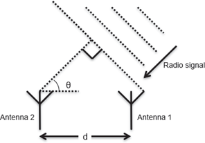
Figure 3 Arrival Angle Detection
When a multi-antenna array receives a signal from a single antenna, the distance varies based on the different arrival angles between the multiple antennas (see Figure 3). If the arrival angle is θ and the distance between the antennas is d, the phase difference f depends on the distance difference dcos(θ), and is given by the formula:f=2лdcos(θ)/λ . Here, λ is the signal wavelength, and the arrival angle θ at the receiving end can be measured from these two antennas, and:θ=arccos((fλ/(2лd)) — note that the distance information d is stored in the configuration of the receiving device.Conversely, when a single antenna receives signals sent by multiple antennas, there is a difference in distance corresponding to the Tx direction of the multiple antennas (see Figure 4). By detecting the phase difference between the antennas on the Rx side, the deviation direction can be found.
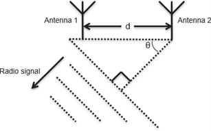
Figure 4 Departure Angle Detection
-
Arrival Angle (AoA)
To detect the arrival direction, as shown in Figure 5, multiple antennas receive the Constant Tone Extension (CTE) portion of the signal sent by a single antenna in time-sharing, and the arrival direction can be found by detecting the phase difference between the antennas. Additionally, the arrival direction can be determined using the phase differences between each antenna since the Rx side knows the positional relationships of the antennas and the switching intervals.
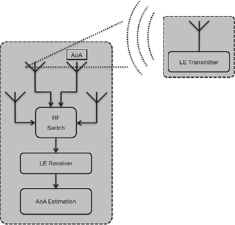
Figure 5 AoA Detection
-
Departure Angle (AoD)
When detecting the departure direction, as shown in Figure 6, a single antenna receives the Constant Tone Extension (CTE) portion of the signal sent by multiple antennas in time-sharing, and the direction can be determined by detecting the phase difference between the antennas. Since the Tx end sends signals at predetermined time intervals and antenna order, the receiving end can determine which signal is from which position and which antenna based on the timing information in the packet header. The side that knows the positional relationships of the antennas and the fixed order (whether Tx or Rx) can find the departure direction from the phase differences between the antennas.
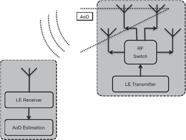
Figure 6 AoD Detection
3. AoA/AoD Physical Layer Test Cases
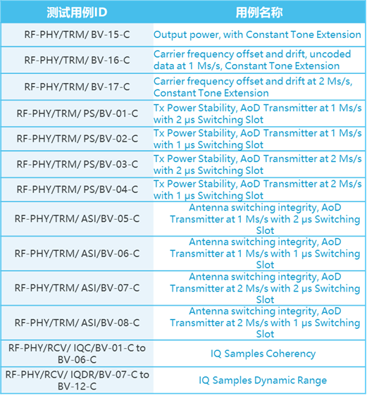
In the AoA and AoD test cases, the Tx and Rx performance of the Constant Tone Extension (CTE) will affect its accuracy. To ensure the accuracy of phase difference detection, the Bluetooth RF testing specifications have added the AoA and AoD RF test cases listed in Table 2.
Table 2 AoA and AoD RF Test Cases (RF-PHY.TS.p15)
-The second part continues-
About Anritsu
-Scan to follow-
Cross Testing

Crossing Limits

5G & IoT | RF Microwave | High-Speed Signal | Wireless Communication | Optical and Digital Communication
Customer Service Hotline 400-879-6892