1. Introduction
Through the introduction of “Bluetooth Protocol Analysis – Protocol Architecture”, everyone should have a simple understanding of the Bluetooth protocol stack, but there is certainly still a feeling of “half-understanding, half-uncertain”. It’s perfectly normal to have this feeling, as the Bluetooth protocol is a long-standing and relatively large protocol that is not easy to understand.
Therefore, this article will take a different perspective and consider the following questions from the viewpoint of the protocol stack designer: Why is there a Bluetooth protocol stack (Why)? How is the Bluetooth protocol stack implemented (How)? What does the final form of the Bluetooth protocol stack look like (What)?
Additionally, we know that the current Bluetooth protocol includes three technologies: BR/EDR, AMP, and LE. To reduce complexity, this article will focus on the currently popular BLE (Bluetooth Low Energy) technology (it’s all about the Internet of Things!), while BR/EDR and AMP can be understood as side topics.
2. Why
The “Why” addresses the issue of demand. For BLE (Bluetooth Low Energy), its demand includes two parts: the overlap with traditional Bluetooth and the unique low-power aspect of BLE. In summary, it includes: wireless communication based on the 2.4GHz ISM band; moderate communication speed requirements but extremely sensitive to power consumption; maximizing the reuse of existing BR/EDR technology; flexible networking methods, allowing both the “connection-based star network (composed of one master and multiple slaves)” used by traditional Bluetooth and the “connectionless mesh network (composed of multiple advertisers and multiple scanners)”; a wide variety of participating communication devices that must be easy to implement and interconnect from an application perspective; strong security needs; and more.
3. How and What
The “How” addresses the design thinking, while “What” refers to the final product designed based on that thinking. Logically, “How” should be introduced first, followed by “What”. However, based on my understanding of Bluetooth, it is clear that one cannot answer “How” without considering “What”. Therefore, it is wise to understand the “How” based on the existing protocol framework (What). Before we start, let’s summarize the BLE protocol framework, which will be analyzed layer by layer using a bottom-up approach in the subsequent chapters. As shown in the image below, the BLE protocol can be divided into two main parts: Bluetooth Application and Bluetooth Core, with Bluetooth Core further comprising BLE Controller and BLE Host (for related concepts, refer to “Bluetooth Protocol Analysis (1) – Basic Concepts”).
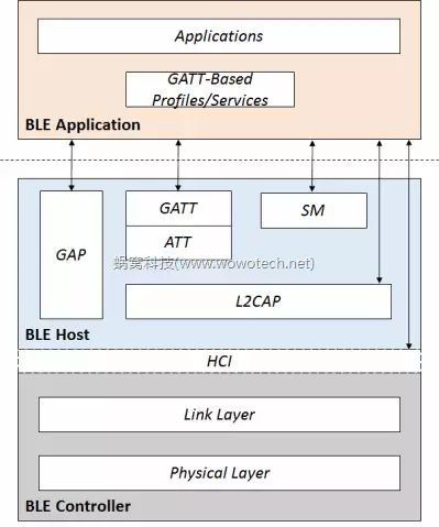
Image 1: BLE Protocol Framework
4. Physical Layer
In any communication system, the first thing to determine is the communication medium (Physical Channel), and BLE is no exception. In the BLE protocol, the definition of the “communication medium” is handled by the Physical Layer (other communication protocols are similar). The Physical Layer describes the communication medium of BLE as follows: since BLE is a wireless communication, its communication medium is a frequency band resource within a certain frequency range (Frequency Band); BLE’s market positioning is individual and civilian, thus using the free ISM band (frequency range is 2.400-2.4835 GHz); to support multiple devices simultaneously, the entire band is divided into 40 parts, each with a bandwidth of 2MHz, referred to as RF Channel.
After the above definition, the physical channels of BLE have been established, which are the 40 RF Channels with frequencies given by “f=2402+k*2 MHz, k=0, … ,39”, each with a bandwidth of 2MHz. Besides the physical channel, the Physical Layer also needs to define some other characteristics of the RF transceiver, including (which do not affect the subsequent discussions in this article and need not be delved into): RF transmission characteristics (Transmitter Characteristics), including transmission power (Transmission power), modulation methods (Modulation), Gaussian Frequency Shift Keying (GFSK), Spurious Emissions, Radio Frequency Tolerance, etc. (which do not affect the subsequent discussions in this article and need not be delved into); RF reception characteristics (Receiver Characteristics), including receiving sensitivity, etc.
5. Link Layer
5.1 Function Introduction
With the definition of the Physical Layer, the physical channels required for communication are ready, namely the 40 RF Channels (hereafter collectively referred to as Physical Channels). At this point, the Link Layer can make its appearance. Its main function is to send and receive data over these Physical Channels, while inevitably needing to control parameters related to RF transmission and reception. However, just doing this is far from sufficient: firstly, the Physical Layer only provides a limited number of 40 Physical Channels, while the number of entities participating in communication in BLE is certainly not at this scale. The Link Layer needs to solve the problem of sharing the Physical Channels; secondly, communication is a matter between two entities, and for these two entities, they hope to see a transmission channel exclusive to themselves (which is what we are familiar with as a logical link, Logical Link). This is also a problem that the Link Layer needs to solve; furthermore, the Physical Channel is unreliable, and any data transmission may be damaged or lost due to interference and other issues, which is unacceptable for some applications. Therefore, the Link Layer needs to provide mechanisms such as verification and retransmission to ensure the reliability of data transmission; and so on, so forth, it is both a father and a mother!
5.2 How to Solve the Sharing Problem of Physical Channels
With only 40 Physical Channels available in a BLE system, how can multiple communication entities be accommodated? It is actually quite simple; the Link Layer divides the communication scenarios of BLE into two categories: 1) Scenarios with relatively small data volumes, infrequent transmissions, and not very sensitive to delays, such as a sensor node (like a temperature sensor) that needs to periodically (like every second) send sensor data (like temperature) to a processing center. For such scenarios, the BLE Link Layer adopts a relatively lazy handling method—broadcast communication: selecting 3 out of the 40 Physical Channels as advertising channels; on the advertising channels, any participant can send or receive data at will, sharing the same logical transmission channel (broadcast channel). Of course, this method has many problems, such as: unreliability, will there be mutual interference? Was the transmission successful? Unknown! Was the reception successful? Unknown! Inefficiency, if there are many nodes in the same area broadcasting data, does a particular receiver have to receive all data packets, regardless of whether they are of interest? Security issues, how to resolve?
Indeed, there are many problems, but the Link Layer has defined some strategies to improve the convenience of this communication method as much as possible, which we will introduce later. As for the unresolved issues, there are two simple solutions: a) endure, as the resources occupied by broadcast communication are minimal, which is just what those small nodes in the Internet of Things crave. b) Use a connection-based communication method (which establishes a dedicated line for you two), which can be referenced in the introduction of section 5.2.2 below.
2) For scenarios with larger data volumes, higher transmission frequencies, and greater sensitivity to delays, the BLE Link Layer will select one from the remaining 37 Physical Channels to establish a separate channel (data channel) for communication between the two parties in this scenario. This is the process of connection (connection). Meanwhile, to increase capacity and enhance anti-interference capabilities, the connection will not permanently use a fixed Physical Channel, but will randomly yet systematically switch between multiple Channels (like 37), which is the frequency hopping (Hopping) technology of BLE. 5.3 State and Role Definitions
Based on the above idea in section 5.2, the BLE protocol abstracts five states in the Link Layer: Note 1: Horizontally, each level of the protocol (like the Link Layer here) can be viewed as an entity that can communicate with each other. The states here refer to the states of each entity at this level. Therefore, there may be state definitions at multiple levels of the protocol, and the names may even be the same; when we read the protocol stack, we must pay attention to this and not get confused. • Standby State • Advertising State • Scanning State • Initiating State • Connection State
And they switch with the following state machine (the device can only be in one of these states at the same time):
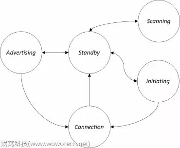
Image 2: Link Layer State Machine
The Standby state is the initial state, where no data is sent or received. Based on commands from upper-level entities (like GAP in host software), it can transition to any other state except the Connection state. The Advertising state is the state where data can be sent via the advertising channel, transitioning from the Standby state. The data broadcasted can be received by entities in the Scanning or Initiating states. The upper-level entity can switch the Advertising state back to Standby state via commands. Additionally, after a successful connection, it can also switch to the Connection state. The Scanning state is the state where data can be received via the advertising channel, transitioning from the Standby state. Depending on the type of data broadcasted by the Advertiser, some Scanners can also actively request additional information from the Advertiser. The upper-level entity can switch the Scanning state back to Standby state via commands. The Initiating state is similar to the Scanning state, but it is a special receiving state, transitioning from the Standby state, which can only receive connectable data broadcasted by the Advertiser and, upon receiving data, send a connection request to establish a connection with the Advertiser. After a successful connection, both the Initiator and the corresponding Advertiser will switch to the Connection state. The Connection state is the state where a dedicated channel has been established with a certain entity, automatically transitioning from either Initiating or Advertising. After the channel is disconnected, it will return to the Standby state. Once the channel is established (commonly referred to as “connected”), both parties in the Connection state have two roles: Master and Slave: the Initiator is referred to as Master; the Advertiser is referred to as Slave.
5.4 Air Interface Protocol
Once the state and role definitions are complete, the remaining tasks are straightforward, mainly including two categories: providing a data exchange mechanism for the corresponding states between entities in a certain state; and switching between states based on commands from upper-level entities and current actual conditions. In the BLE protocol, these tasks are handled by a component called the Air Interface Protocol, with the main ideas as follows.
5.4.1 Defining the Packet Format for Sending and Receiving Data on Physical Channels
In BLE, both types of Physical Channels (advertising channel and data channel) use a unified packet format, as follows: Preamble (1 octet) Access Address (4 octets) PDU (2 to 257 octets) CRC (3 octets)
Regarding the packet format, we can focus on the following aspects: 1) Access Address, used for identification. 2) PDU, the maximum length of the PDU in the Link Layer of BLE is 257 octets (not sure what octets mean? Treat them as bytes). This determines that upper-level entities, such as L2CAP, Application, etc., need to split and reassemble to support larger data transmissions. 3) The total packet length in the Link Layer is 9-264 bytes.
5.4.2 Defining Different Types of PDUs and Their Formats
Based on the description in section 5.3, the Link Layer has five states, and the functions of the data transmitted under each state vary. Based on this, the Air Interface Protocol defines the following PDU types (only a brief listing here, without in-depth discussion): 1) Advertising-related PDUs in the advertising channel
ADV_IND, Broadcast data sent by the Advertiser, which is connectable and undirected. ADV_DIRECT_IND, Broadcast data sent by the Advertiser, which is connectable and directed. ADV_NONCONN_IND, Broadcast data sent by the Advertiser, which is non-connectable and undirected. ADV_SCAN_IND, Broadcast data sent by the Advertiser, which is scannable and undirected.
2) Scanning-related PDUs in the advertising channel
SCAN_REQ, Data packet sent by the Scanner to request additional information from the Advertiser (generally sent after receiving ADV_SCAN_IND). SCAN_RSP, Data packet sent by the Advertiser in response to SCAN_REQ.
3) Initialing-related PDU in the advertising channel
CONNECT_REQ, Data packet initiated by the Initiator to request establishing a connection.
4) LL data-related PDUs in the data channel
PDU used for data communication between connected parties, with an effective payload length of 0-251 bytes.
5) LL control-related PDUs in the data channel
PDU used to manage, maintain, and update the established data channel, including: LL_CHANNEL_MAP_REQ, a request to change the Physical Channel being used; LL_TERMINATE_IND, notifying the other party that the connection is about to end and the reason for ending; and so on.
5.4.3 Defining the Data Filtering Mechanism of the Link Layer in the Form of a Whitelist
This mainly targets the advertising channel, as the number of communication devices increases, the broadcast data in the air will grow geometrically. To avoid wasting resources (especially BLE Host), it is necessary for the Link Layer to filter out some data packets, for example, filtering out packets that are not intended for oneself based on Bluetooth addresses. 5.4.4 Executing Actual Packet Sending and Receiving Operations on the Advertising Channel
The upper-level software only needs to define some parameters, such as: the selection of the Advertising Channel under the Advertising State, the advertising interval, the type of Advertising PDU, etc.; in the Scanning State/Initialing State, the scan window, scan interval, etc.
The Link Layer will automatically send or receive data packets.
5.4.5 Defining the Connection Establishment Method and Subsequent Response, Flow Control, and Other Mechanisms
Details are not described here.
5.5 Link Layer Control
After the abstraction of the Air Interface Protocol, the BLE entities have basic capabilities for broadcast communication, establishment and release of point-to-point connections, and point-to-point communication. In addition, the Link Layer has abstracted a Link Layer Control protocol to manage and control the established Connection between two Link Layer entities. Its main functions include updating Connection-related parameters, such as transmit window size, transmit window offset, connection interval, etc. (specific meanings are not elaborated here); updating the frequency hopping map used for that connection (which Physical Channels to use); and executing link encryption processes.
6. HCI
Defines the communication protocol between the Host and Controller (usually two ICs), which can be based on physical media like UART, USB, etc. This is not essential for understanding the Bluetooth protocol, so it will not be introduced here.
7. L2CAP Protocol
7.1 Function Introduction
After the abstraction of the Link Layer, there can be two logical data channels between two BLE devices: one is the connectionless broadcast channel, free as a bird; the other is the connection-based data channel, which is a point-to-point (Master to Slave) logical channel. Leaving the broadcast channel aside, this data channel (hereafter referred to as logical channel) requires further thought on how to use it. For instance: there is only one Logical Channel, while the upper-level applications that need to use it are certainly more than one (like ATT and SMP in Image 1); how to multiplex? The maximum effective payload length that the Logical Channel can transmit is only 251 bytes; does this mean that upper-level applications can only transmit data less than this length each time? (Clearly not!) The Logical Channel only provides simple acknowledgment and flow control mechanisms; what if the transmitted data is erroneous? And so on…
These issues are all addressed by L2CAP, a protocol that exists between the application (Profile, Application, etc.) and the Link Layer, which is what its abbreviation (Logical Link Control and Adaptation Protocol) signifies. The main functions it provides include: Protocol/channel multiplexing; Segmentation and reassembly of upper-level application data (L2CAP Service Data Units, SDUs) into protocol data units (L2CAP Packet Data Units, PDUs) to meet the latency requirements of user data transmission and facilitate subsequent retransmission and flow control mechanisms; Flow control per L2CAP channel; Error control and retransmissions; Support for Streaming (such as audio, video, etc., which do not require retransmission or only require limited retransmission); Fragmentation and Recombination of protocol data units (PDUs) into data segments that meet Link Layer transmission requirements (length not exceeding 251, specific reference can be made to section 5.4.1); Quality of Service support.
Due to space limitations, this article will focus on the “Protocol/channel multiplexing” function that aids in understanding upper-level protocols (ATT, GATT, etc.). Other parts will be highlighted in subsequent articles analyzing L2CAP.
7.2 Protocol/channel multiplexing
Multiplexing is quite easy to understand: there is only one logical link available for transmitting user data, while the number of upper-level Profiles and Applications that L2CAP needs to serve is certainly far greater than this. Therefore, multiplexing methods must be used to map these user data onto the limited link resources.
As for the method of multiplexing, it is simple and straightforward (considered a standard feature of a protocol): when sending data, the user data is divided into packets of a certain length (L2CAP Packet Data Units, PDUs), with a header containing a specific “ID” added, and sent out via the logical link. When receiving data, it is received from the logical link, the “ID” is parsed, and based on this, it is determined which application the data should be forwarded to.
The “ID” referred to here is the means of multiplexing, and L2CAP provides two multiplexing methods:
7.2.1 Connection-based Method (here, connection refers to the L2CAP connection, do not confuse it with the Link Layer connection)
This connection refers to an application based on L2CAP establishing a virtual channel based on the Logical Channel (called L2CAP channel, similar to ports in TCP/IP) before communication. L2CAP will assign a number to this channel, called channel ID (CID for short). Once the L2CAP channel is established, the CID can be placed in the packet header to achieve multiplexing. This multiplexing based on CID is called channel multiplexing. How is the CID determined? Some fixed-purpose L2CAP Channels have fixed values, while others are dynamically allocated, as follows:
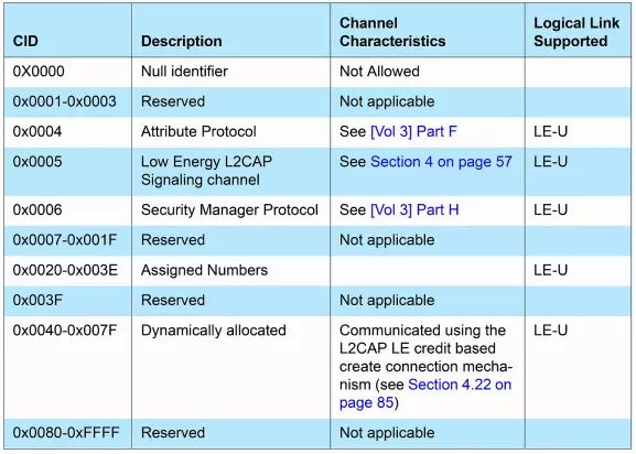
Image 3: BLE CID Allocation
For specific CID values, refer to: Core_v4.2.pdf, Volume 3, Part A – Logical Link Control and Adaptation Protocol Specification
7.2.2 Connectionless Method
Additionally, to improve data transmission efficiency and facilitate applications such as broadcast communication, L2CAP provides a connectionless data transmission method in addition to the connection-based communication mechanism. In this method, there is no CID; instead, there is a field called Protocol/Service Multiplexer (PSM). This method of multiplexing is called Protocol multiplexing. Since Protocol multiplexing is only allowed to be used in BR/EDR controllers, it will not be detailed here.
8. Attribute Protocol
From the descriptions in the above chapters, it can be seen that in the BLE protocol stack: the Physical Layer is responsible for providing a series of Physical Channels; based on these Physical Channels, the Link Layer can establish Logical Channels for point-to-point communication between two devices; and L2CAP divides this Logical Channel into multiple L2CAP Channels to provide application-level channel multiplexing. At this point, the basic protocol stack has been constructed, and applications can happily run based on L2CAP. Speaking of applications, we must mention the original intention of BLE— the Internet of Things. What is the difference between the data transmitted in the Internet of Things and that in the traditional internet? Leaving other factors aside, one of the most important and widespread applications in the Internet of Things is: information collection.
This information is often very simple, such as temperature, humidity, speed, location information, battery level, water pressure, etc. The collection process is also very simple, where node devices periodically report information data to a central device or the central device actively queries when needed.
Based on the demand for information collection, BLE abstracts a protocol: the Attribute Protocol, which abstracts this “information” in the form of “Attributes” and provides methods for remote devices to read and modify these attribute values (Attribute value). The main ideas of the Attribute Protocol include: 1) Based on L2CAP, using a fixed Channel ID (0x004, specific reference can be made to “Image 3”). 2) Adopting a client-server model. The party providing the information (which will be referred to as Attribute in the future) is called the ATT server (usually those sensor nodes), while the party accessing the information is called the ATT client. 3) An Attribute consists of Attribute Type, Attribute Handle, and Attribute Value.
Attribute Type is used to indicate the type of Attribute, similar to terms that humans can recognize such as “temperature”, “humidity”, etc. However, unlike human terms, Attribute Type is distinguished using UUID (Universally Unique Identifier, which can be 16-bit, 32-bit, or 128-bit values). Attribute Handle is a 16-bit value used to uniquely identify all Attributes on the Attribute server. The existence of the Attribute Handle has the following significance: a) A server may have multiple Attributes of the same type, and clearly, the client needs to distinguish these Attributes. b) Multiple Attributes of the same type can form a Group, allowing the client to access all Attributes through the starting and ending handles in this Group. Attribute Value represents the value of the Attribute and can be any fixed-length or variable-length octet array (understood as an array of bytes).
4) Attributes can define some permissions (Permissions) to allow the server to control client access behavior, including: access permissions (access permissions), Readable, Writeable, and Readable and writable; encryption-related permissions (encryption permissions), Encryption required and No encryption required; authentication-related permissions (authentication permissions), Authentication Required and No Authentication Required; authorization-related permissions (authorization permissions), Authorization Required and No Authorization Required.
5) Based on the different defined Attribute PDUs, the client can have multiple access methods to the server, including: Find Information, obtaining the correspondence between Attribute type and Attribute Handle; Reading Attributes, including Read by type, Read by handle, Read by blob (only reading part of the information), Read Multiple (reading multiple handles’ values); Writing Attributes, including writing that requires acknowledgment and writing that does not require acknowledgment.
9. Generic Attribute Profile
9.1 Function Introduction
ATT is referred to as a “protocol” because it is still relatively abstract and only defines a mechanism that allows clients and servers to share information in the form of Attributes. However, what specific information is shared is not the concern of ATT; this is the domain of GATT (Generic Attribute Profile). GATT adds one more ‘G’ to ATT, but its meaning is vastly different, as GATT is a profile (more accurately, a profile framework). In the Bluetooth protocol, the profile has always been a relatively abstract concept, which we can understand as an Application whose “application scenario, function, and usage method” are predefined. This is true for traditional BR/EDR and even more so for BLE. As mentioned earlier, a significant part of BLE’s application scenarios is the sharing of information (Attributes). Therefore, the BLE protocol stack, based on the Attribute Protocol, defines a profile framework called GATT (Generic Attribute) to provide general functions for information storage and sharing.
9.2 Hierarchical Structure
As a Profile framework, the GATT profile proposes the following hierarchical structure:
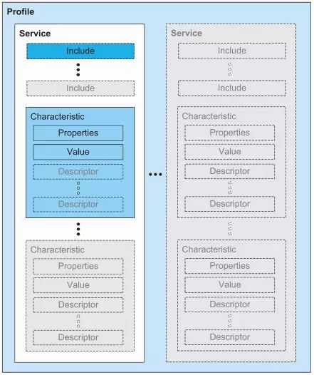
Image 4: GATT Profile Hierarchy
From the image above, it can be seen that the hierarchical structure of the GATT profile is: Profile—> Service—> Characteristic. “Profile” is the actual Profile derived from GATT, located at the top of the GATT Profile hierarchy, composed of one or more Services related to a specific application scenario. A Service contains one or more Characteristics, and it can also include other Services through the Include method. A Characteristic is the most basic data unit in the GATT profile, consisting of Properties, a Value, and one or more Descriptors. Characteristic Properties define how the characteristic’s Value can be used and how the characteristic’s Descriptors can be accessed. Characteristic Value is the actual value of the characteristic; for example, for a temperature characteristic, its Characteristic Value is the temperature value. Characteristic Descriptors store some information related to the Characteristic Value (which is quite abstract and will be further understood in subsequent articles based on examples). Each definition except for “Profile”—such as Service, Characteristic, Characteristic Properties, Characteristic Value, Characteristic Descriptor, etc.—exists as an Attribute and possesses all the characteristics of Attributes described in Chapter 8: Attribute Handle, Attribute Types, Attribute Value, and Attribute Permissions.
9.3 Important Considerations
The GATT profile introduced after Bluetooth 4.0 is a very “clever” profile, and there are three points that we need to pay special attention to: 1) Based on the GATT architecture, the existence form of Applications is no longer a single Profile; many simple application scenarios can exist directly as Services (the concept of profile is hidden within GATT), which greatly simplifies the design complexity of some sensor nodes. 2) Take a close look at the Services in Image 4 and recall the “Service” in the Bluetooth BR/EDR Service Discovery Protocol (SDP); is there any connection? You guessed it, there is a significant connection. In the implementation of GATT, there is no longer a need for SDP. A Service is also an ordinary Generic Attribute. It is precisely because of this abstraction that the “Service” in the previous Bluetooth protocol has been instantiated. 3) The so-called “Service” instantiation means that any profile consists of Services and the corresponding Profile functions.
10. Security Manager (SM)
The Security Manager is responsible for security-related matters in BLE communication (undoubtedly, security becomes more important in the era of the Internet of Things; no one wants their bedroom lights to turn on inexplicably in the middle of the night), including pairing, authentication, and encryption processes. This part is relatively independent, so we will not elaborate further; later, there will be a separate analysis article.
11. Generic Access Profile (GAP)
Chapters 7 to 10 above are related to the data channel based on connections. As for the connectionless advertising channel and the connection establishment process, it seems we have overlooked them. Although the Link Layer has made definitions (specific reference can be made to Chapter 5), they do not reflect at the Application (or Profile) level, as the Link Layer is too low-level.
Therefore, the BLE protocol stack defines a profile called Generic Access to achieve the following functions: 1) Define the roles of Bluetooth devices at the GAP layer (roles similar to those in the Link Layer in section 5.3), but the roles at the GAP layer are closer to the user (can be equated to the roles of Bluetooth devices from the user’s perspective), including: Broadcaster Role, the device is sending advertising events; Observer Role, the device is receiving advertising events; Peripheral Role, the device accepts Link Layer connections (corresponding to the slave role in the Link Layer); Central Role, the device initiates Link Layer connections (corresponding to the master role in the Link Layer).
2) Define operational modes and procedures for various communications at the GAP layer, including: Broadcast mode and observation procedures, achieving one-way, connectionless communication; Discovery modes and procedures, implementing Bluetooth device discovery operations; Connection modes and procedures, implementing Bluetooth device connection operations; Bonding modes and procedures, implementing Bluetooth device pairing operations.
3) Define Bluetooth parameters related to the User Interface, including: Bluetooth address; Bluetooth name; Bluetooth passkey; Bluetooth class (related to transmission power); and so on.
4) Security-related definitions are not introduced here.
12. Applications
Not introduced here; subsequent articles will further analyze some Profiles and application scenarios.
Source: Wowo Technology
[Recommended Reading]
Bluetooth Protocol Analysis – Protocol Architecture
Starting from the levels of autonomous driving, let’s take a look at the differences between autonomous driving and assisted driving.
The 3W rule and 20H principle in PCB design
The principles and application scenarios of LQ and RSSI in Bluetooth protocols
Murata’s first mass-produced 1210 size, 100V voltage multilayer ceramic capacitor with a capacitance of 10μF