
Abstract
Currently, robotics education in China is primarily theoretical, with limited practical opportunities. It is necessary to provide economical and practical experimental devices to guide students in engaging with artificial intelligence algorithms and robot control. This intelligent car uses the AT-SAMD21G18A chip as its core, utilizing four photoresistors to collect light intensity information, and selects an artificial neural network as the control algorithm to drive two DC geared stepper motors to execute movement commands, achieving light-seeking and light-avoiding functions. Experimental results show that although the device has a simple structure, it covers the basic knowledge of artificial neural networks and robotics applications, providing a low-cost and scalable hardware support for robotics experimental teaching.
Keywords
Artificial Intelligence; Light Intensity; Neural Network; Robotics Education

With the advent of the artificial intelligence era, the trend of intelligence in robotic products has become increasingly evident. On March 21, 2016, the Ministry of Industry and Information Technology, the National Development and Reform Commission, and the Ministry of Finance jointly issued the “Robot Industry Development Plan (2016-2020)”, outlining a clear blueprint for the development of China’s robot industry during the 13th Five-Year Plan period. On July 8, 2017, the State Council issued the “New Generation Artificial Intelligence Development Plan”, clarifying the strategic goals for the development of a new generation of artificial intelligence in China. In response to national strategic priorities, many universities have successively launched robotics-related courses.However, conducting robotics experimental teaching requires support in terms of funding for robot purchases and experimental venues. Due to differences in educational conditions, most institutions’ teaching explorations still focus on theoretical teaching and virtual simulation experiments, with limited physical robot operations constrained by closed hardware, making it difficult to expand. Students can easily lose interest after initial enthusiasm. On the other hand, having learning capabilities is the primary condition for robots to possess intelligence, and the learning ability of robots is closely related to one of the hot topics in artificial intelligence research—artificial neural networks. Currently, domestic teaching practices related to neural networks often use open-source artificial intelligence frameworks such as TensorFlow and Caffe. While this format facilitates engineering applications and research, its high level of encapsulation is not suitable for basic teaching. Therefore, it is essential to design a low-cost experimental device that integrates the fundamental theory of neural networks and the practical application of robotics.The intelligent car in this design detects the external environment’s light intensity information through photoresistors and uses a BP neural network to control the movement of DC geared stepper motors, achieving light-seeking and light-avoiding control in robot benchmark tests. This design complies with the open-source hardware Arduino specifications, making it easy to deploy on other compatible hardware platforms. The construction and configuration of the artificial neural network are also relatively flexible, allowing students to customize and expand functions based on their interests by selecting sensors and actuators. The experimental device has a simple structure and intuitive principles, providing a beneficial supplement to existing robotics experimental teaching and offering significant reference value for guiding students to master the basic knowledge of intelligent robots.
1
System Design
The purpose of this design is to provide a low-cost experimental device suitable for robotics education while incorporating fundamental knowledge of artificial intelligence and robotics control applications. Therefore, during the overall design, we fully considered utilizing resources from the open-source community and set reasonable target functions based on conventional robot testing tasks to highlight the characteristics of intelligence, physicality, and scalability of the device.First, the hardware design adheres to the open-source philosophy and complies with Arduino specifications. Arduino, as an Italian educational open-source hardware project, has the advantage of completely open technical documentation, rich module functions, and an active community, making compliant designs convenient for students to engage in self-directed learning and later functional expansion. Secondly, in software design, the most commonly used BP neural network in artificial intelligence applications was selected as the control algorithm, and the code implementation does not rely on third-party frameworks, making the details of neural network construction, configuration, and training fully visible. Furthermore, the functional settings selected common light-seeking and light-avoiding tests from robot benchmark tests as target tasks, which are representative. Finally, a combination of virtual and physical methods applies theoretical intelligent algorithms to control physical hardware, allowing for the verification of various intelligent algorithms (such as BP neural networks, Boolean networks, etc.).The intelligent car is implemented based on an embedded system, with photoresistors and stepper motors corresponding to the input layer nodes and output layer nodes of the neural network, respectively. The system framework is shown in Figure 1.
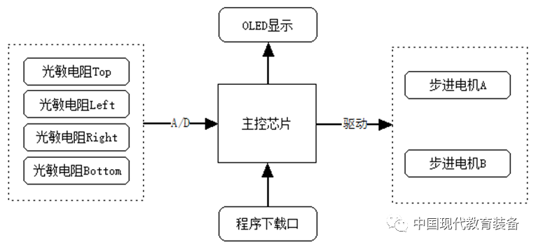
Figure 1 System FrameworkThe intelligent car uses photoresistors as the light intensity detection module, and the light intensity signals collected are processed by the main control chip to control the operation of the stepper motors, achieving intelligent interaction between the car and the external environment.
2
System Hardware Design
The system hardware circuit mainly includes the processor, photoelectric detection circuit, motor drive circuit, display circuit, and program download circuit. Considering the reasonable utilization of existing resources from the Arduino community and future scalability, the hardware resources defined below are compatible with the Arduino Zero (M0) development board.1. Main Control ChipThe main control chip selected is Atmel’s SAMD21G18A microcontroller, which uses a 32-bit ARM Cortex M0+ core, has 256 KB of flash memory, 32 KB of SRAM, and a system clock frequency of up to 48 MHz, with a built-in 12-bit analog-to-digital converter, meeting the performance requirements for computation, storage, signal acquisition, and conversion in this design.2. Photoelectric Detection CircuitThe photoelectric detection circuit includes four photoresistors connected to the analog ports PA04, PA05, PB08, and PB09 of the main control chip to detect the intensity signals of ambient light from different directions. The circuit diagram is shown in Figure 2.
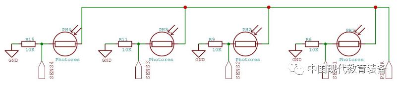
Figure 2 Photoelectric Detection Circuit DiagramThis design uses the PDV-P8001 photoresistor as the photoelectric detection element, primarily because it can sense visible light with wavelengths from 400 to 700 nm, with a dark resistance of 0.2 MΩ, a bright resistance of 3 to 11 KΩ, and a sensitivity of 0.8 Ω/Lux, which is smaller in bright resistance, larger in dark resistance, and higher in sensitivity than common photoresistors, meeting the design requirements.3. Motor Drive CircuitThe motor drive circuit uses the DRV8835 motor driver chip, which has two H-bridges that can support two stepper motors. The input terminals are connected to the main control chip’s PA20, PA15, PA09, and PA08 to receive motor drive commands from the main control chip; the output terminals are connected to stepper motors A and B to achieve motion control. The specific circuit is shown in Figure 3.
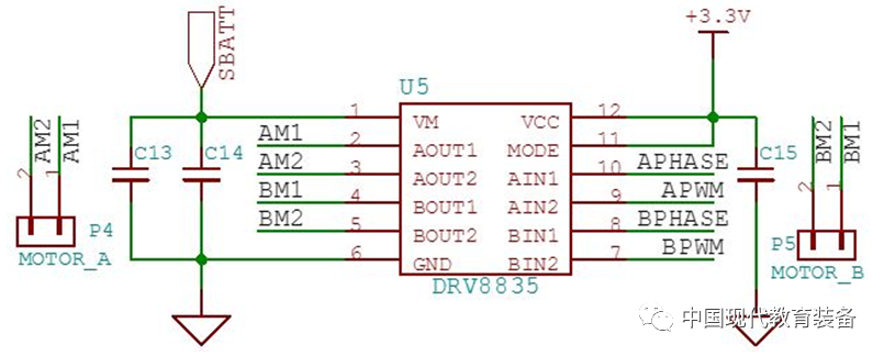
Figure 3 Motor Drive CircuitThe DRV8835 selected in this design is a low-voltage dual H-bridge motor driver, with each H-bridge capable of supplying up to 1.5 A of output current, operating within a motor power supply voltage range of 0 to 11 V and a device power supply voltage range of 2 to 7 V, making it very suitable for low-voltage or battery-powered motor control applications.4. Display CircuitThe display circuit is mainly used to show necessary debugging and operational information during human-machine interaction. In this design, a 0.66-inch OLED display module is used, utilizing a 7-pin single-row socket to connect the main control chip’s PA16, PA18, PA19, PA06, and PA07 as an SPI interface. The specific circuit is shown in Figure 4.
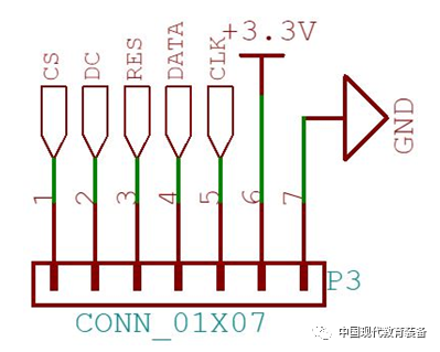
Figure 4 Display Circuit Interface Diagram5. BootLoader Download CircuitThe BootLoader download circuit design is compatible with Arduino specifications. When using Arduino, a Bootloader program is required to complete the chip initialization work. For the SAMD21 series processors, the Atmel-ICE programmer is needed to burn the Bootloader program. This programmer uses a 10-pin ISP download port, so a 10-pin single-row socket is used in the circuit to connect the main control chip’s PA30 and PA31 as SWDIO and SWCLK. The circuit diagram is shown in Figure 5.
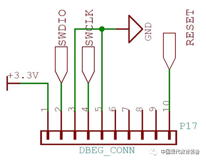
Figure 5 BootLoader Download Circuit Diagram6. Power Supply and Data Interface CircuitThis design provides two power supply methods: USB and a 3.7 V lithium battery. The USB interface not only powers the system but also allows for user program downloads. In the Arduino specifications, user programs need to be downloaded via USB; therefore, this design uses a 5-pin USB OTG connector to connect the main control chip’s PA24 and PA25 for data input and output. Additionally, a voltage regulator chip AP2112 is used for step-down, providing a stable 3.3 V power supply for the system. The specific circuit is shown in Figure 6.
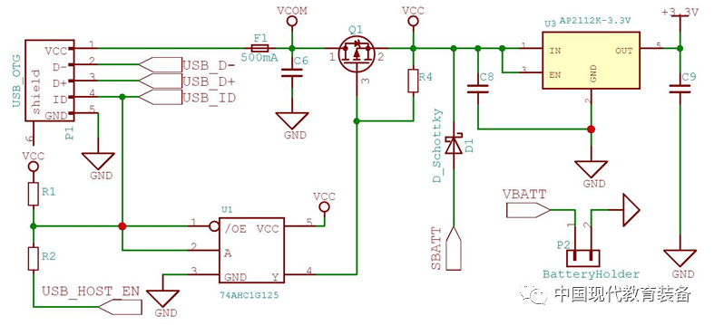
Figure 6 Power Supply and Data Interface Circuit DiagramIn addition to the main functional circuits mentioned above, the intelligent car also includes auxiliary components such as buttons, which will not be elaborated on here. The assembled intelligent car is shown in Figure 7. The entire design is compact, simple in structure, and clear in principle, with the most significant difference from ordinary intelligent cars being the use of the BP neural network as the core control algorithm, endowing it with preliminary intelligent decision-making capabilities.
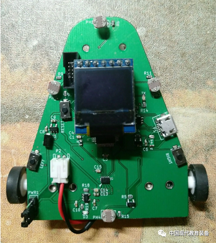
Figure 7 Hardware Physical Diagram
3
System Software Design
The system software encompasses multi-channel ADC data measurement, neural network training, motor control, information display, and other content. The main program flowchart of the system is shown in Figure 8.
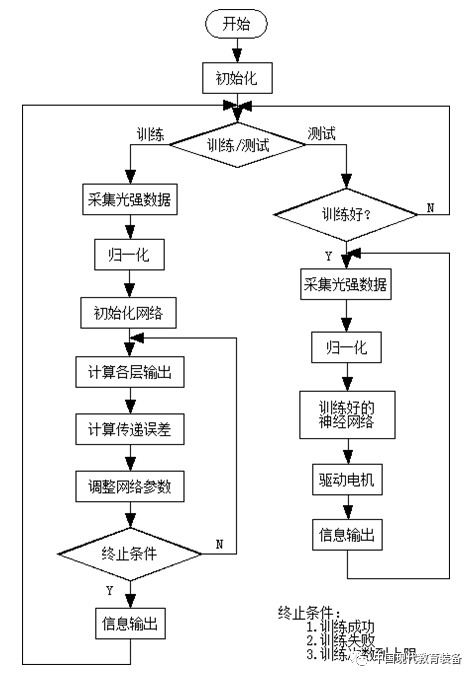
Figure 8 Main Program FlowchartUsing the photoresistors distributed in the front, back, left, and right directions of the car, the light intensity information of the environment is collected. The built-in 12-bit analog-to-digital converter of the processor converts the voltage across the photoresistors to obtain the light intensity, reflecting the lighting conditions of the environment where the car is located. During the training phase, students use this environmental information to achieve autonomous learning and adjust the parameters of the neural network; during the testing phase, based on the trained BP neural network, the speeds and directions of the two stepper motors are coordinated to control the movement of the car, enabling it to respond intelligently to the environment. Training and testing information is transmitted to the OLED for display via the SPI interface.
4
BP Neural Network Algorithm
An important feature of artificial neural networks is their ability to improve system performance through learning from the environment. Performance improvement is gradually achieved by adjusting the system’s parameters, specifically the connection weights between neurons and their respective thresholds. In practical applications of artificial neural networks, over 70% of them use BP neural networks.This intelligent car selects common light-seeking and light-avoiding tests from robot benchmark tests in its functional settings, using only four photoresistors and two low-voltage geared stepper motors, resulting in a relatively simple overall structure. Based on these settings, a three-layer BP neural network was constructed, with the number of neurons in the input layer, hidden layer, and output layer being 4, 5, and 2, respectively, where the hidden layer node count of 5 was found to meet the requirements, and the transfer function between layers was the Sigmoid function.As a key to training the neural network, while the backpropagation algorithm involves some advanced mathematical knowledge, the basic concept is quite simple, and it will not be elaborated on here due to space constraints. Below, only the network configuration information and training data generation method for implementing the light-avoiding task are provided (see Table 1).Table 1 Network Configuration Information
|
LearningRate |
Momentum |
InitialWeightMax |
Success |
|
0.3 |
0.9 |
0.5 |
0.0015 |
In the table, LearningRate is the learning rate, Momentum is the gradient descent momentum, InitialWeightMax is the maximum initial value of the network connection weights, and Success is the threshold for judging training success. These parameters can be configured as needed to observe and compare training effects under different configurations.During neural network training, the dataset consists of input samples and corresponding target output samples. The input samples of this design are stored in the array Input[16][4], where each row represents the light intensity in the front, left, right, and back directions, with 0 indicating the lower limit of measured light intensity and 1 indicating the upper limit. For example, {0, 1, 1, 0} indicates that the light intensity on the left and right sides reaches the upper limit, while the front and back sides reach the lower limit. The array contains 16 rows, listing all possible extreme situations. The corresponding target output samples are stored in the array target[16][2], where each row represents control commands for the left and right stepper motors, such as {0.65, 0.55}. For ease of processing, the output samples are also normalized, with values ranging from 0 to 1, where 0.5 indicates a stop, values greater than 0.5 control the motor to rotate forward, and values less than 0.5 control the motor to rotate backward. It is important to note that the training data available for use during training is derived from these 16 patterns, and to reduce local optimum situations, the training samples used in each iteration should be shuffled.
5
Device Testing Results
After the software and hardware design of the intelligent car is completed, it constitutes a complete experimental device. During testing, the collected light intensity signals from the four directions are normalized and input into the neural network, and then, based on the task, the control commands for the left and right stepper motors are coordinated to achieve light-seeking and light-avoiding functions. Figure 9 shows the display output results when covering the photoresistors in different directions, and Figure 10 shows the effect of the light-avoiding test, where the car autonomously chooses to hide in a darker area.
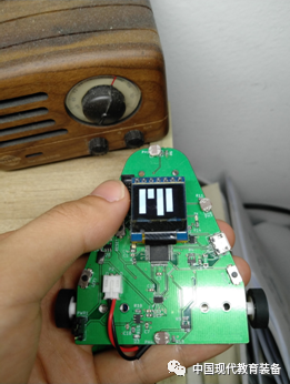
Figure 9(a) Covering the Front
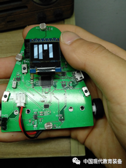
Figure 9(b) Covering the Left Side
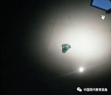
Figure 10 Light-Avoiding TestThis intelligent car successfully implements light-avoiding and light-seeking tests. Due to the system’s openness, students can easily transplant the algorithms directly to other Arduino-compatible hardware platforms, add more sensors and actuators according to task requirements, build their own network structures, and use this system to verify other intelligent control algorithms.
6
Conclusion
This article details a design scheme for an intelligent car aimed at robotics education. The design features a simple structure and intuitive principles, applying a typical BP neural network to control the car, adhering to Arduino’s open-source specifications, facilitating students’ self-directed learning and expansion, and providing significant reference value for helping students master artificial intelligence algorithms and enriching robotics experimental teaching methods.

Welcome to subscribe to the magazine “Modern Educational Equipment in China!”
References
[1] Song Huixin. Keywords for the Future Development of China’s Robot Industry—Interpretation of the “Robot Industry Development Plan (2016-2020)” [J]. Automation Expo, 2016(9):30-31.
[2] “New Generation Artificial Intelligence Development Plan” [J]. Science and Technology Guide, 2018, 36(17):113.
[3] Wang Tingting, Ren Youqun. Talent Strategy in the Era of Artificial Intelligence—Interpretation of the “Higher Education Artificial Intelligence Innovation Action Plan” [J]. Distance Education Journal, 2018, 36(5):52-59.
[4] Zhang Rui, Jiang Ming, Liu Xueliang, et al. Teaching Research on the Course of “Robot Control Technology” [J]. Scientific Consultation (Education Research), 2019(1):24-25.
[5] Li Xuan, Xia Jun, Li Changjiang, et al. Research on the Current Situation and Countermeasures of Robotics Education Development in Colleges and Universities [J]. Electronic World, 2017(13):7-8.
[6] Zhang Ben. Exploration of Practice-Oriented Robotics Teaching Reform [J]. China Educational Technology Equipment, 2017(6):91-92.
[7] Wu Zhenyu, Liu Yutong, Feng Lin. Exploration of Robotics Practical Teaching System Reform [J]. Laboratory Research and Exploration, 2017, 36(6):192-195.
[8] Xia Yulu. Overview of the Development of Artificial Neural Networks [J]. Computer Knowledge and Technology, 2019, 15(20):227-229.
[9] Sun Zhijun, Xue Lei, Xu Yangming, et al. Overview of Deep Learning Research [J]. Computer Application Research, 2012, 29(8):2806-2810.
[10] Ruan Xiaogang, Pang Tao, Yu Jianjun. Robot Light-Seeking Control Based on Boltzmann Machine Neural Network Cognition Mechanism [J]. Control and Decision, 2014, 29(12):2189-2194.
[11] Pang Tao, Ruan Xiaogang, Chen Jing, et al. Robot Light-Seeking Control Based on Internal Engine Mechanism [J]. Journal of Beijing University of Technology, 2014, 40(1):32-37.
[12] DAI L Z, RUAN X G, WANG G W, et al. Neural networks based autonomous learning for a desktop robot [P]. Intelligent Control and Automation (WCICA), 2012 10th World Congress on, 2012.
[13] Yang Nan. Research on Intelligent Product Prototype Design Based on Arduino [D]. Wuxi: Jiangnan University, 2014.
[14] Cui Caihao, Zhang Yuhua, Yang Shucai. Design of a Light-Guided Mobile Car Using Arduino Control Board [J]. Automation Instrumentation, 2011, 32(9):5-7,11.
[15] ROLI A, MANFRONI M, PINCIROLI C, et al. On the design of Boolean network robots [C]//European Conference on the Applications of Evolutionary Computation. Springer, Berlin, Heidelberg, 2011: 43-52.
[16] Arduino and Atmel Release Arduino Zero Development Board [J]. Microcontroller and Embedded Systems, 2014, 14(7):87-88.
Author Information:
Zhang Xiaohua, PhD in Engineering, Lecturer, College of Physics and Electronics, North China University of Water Resources and Electric Power, 450046;
Bai Juan, Master of Engineering, Lecturer, College of Information Engineering, North China University of Water Resources and Electric Power, 450046.
Statement: The figures and tables in this article are provided by the author and may not be used without authorization.
The original text was published in the magazine “Modern Educational Equipment in China”, September 2021, Issue 17.
Editor | Zhang Sai
Typesetting | Zhao Qilong
Review | Pei Jun
Release | Zhang Xin
Cover image material sourced from the internet

* Any reprints of messages published by the WeChat public account of Modern Educational Equipment in China must be fully credited and include the above QR code; otherwise, legal action will be pursued.

Click “Read the original text”
Enter the official website of “Modern Educational Equipment in China” magazine