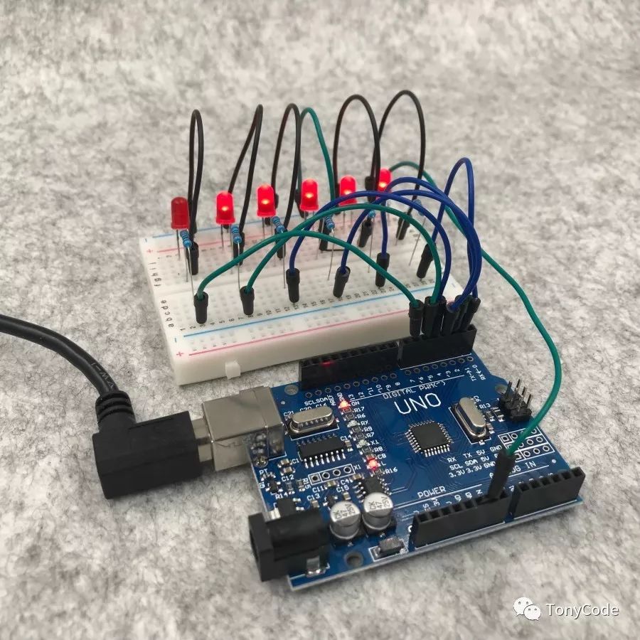
Reading this article will take about 3 minutes.
The previous article introduced the Arduino digital I/O pins and related functions, lighting up the onboard LED. This article will use a breadboard to build a circuit, allowing multiple LEDs to create a flowing effect.
1. Experimental Materials
-
Uno R3 Development Board
-
USB Data Cable
-
Breadboard and Jumper Wires
-
6 LEDs
-
6 x 220Ω Resistors
2. Experimental Steps
-
Build the circuit according to the schematic.
Through-hole LEDs have two pins; the longer pin is positive, and the shorter pin is negative. The LED lights up when current flows from the positive to the negative. The negative pins of the 6 LEDs are connected to the GND pin of the development board, while the positive pins are connected through 220Ω resistors to the digital I/O pins of the board.
The experimental schematic is shown in the figure below:
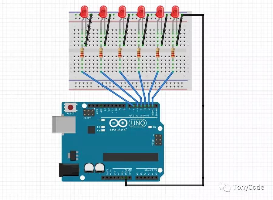
Flowing LED Circuit Connection Diagram The physical connection diagram is shown in the figure below:
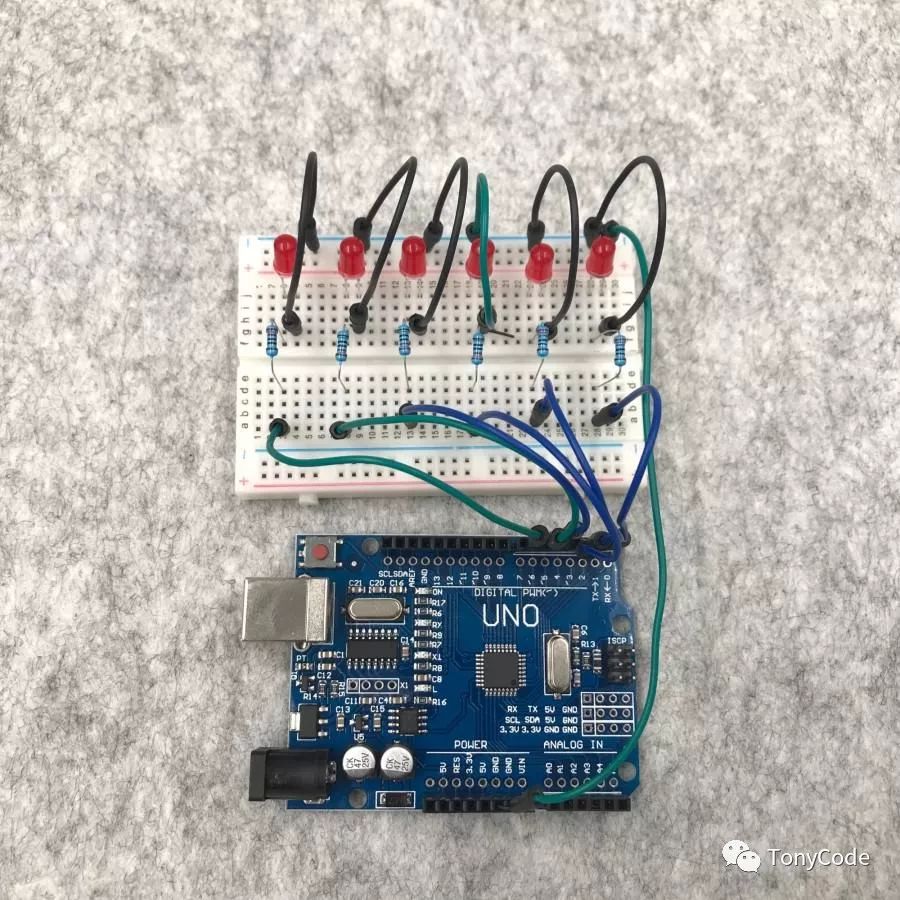
Physical Connection Diagram -
Create a new sketch and replace the auto-generated code with the following code, then save it.
1/* 2 * Led_Flash 3 * Light up LEDs 1 to 6 in sequence and turn off LEDs 6 to 1 in sequence, repeating this cycle. 4 */ 5 6int delayTime = 200; 7int ledPin; 8 9void setup() 10{ 11 for (ledPin = 1; ledPin < 7; ledPin++) // Set pins 1 to 6 as output 12 { 13 pinMode(ledPin, OUTPUT); // Set the ledPin as output 14 } 15} 16void loop() 17{ 18 for (ledPin = 1; ledPin < 7; ledPin++) // Light up LEDs connected to pins 1 to 6 at intervals of delayTime 19 { 20 digitalWrite(ledPin, HIGH); // Light up the LED connected to ledPin 21 delay(delayTime);// Wait for delayTime 22 } 23 24 for (ledPin = 6; ledPin > 0; ledPin--) // Turn off LEDs connected to pins 6 to 1 at intervals of delayTime 25 { 26 digitalWrite(ledPin, LOW); // Turn off the LED connected to ledPin 27 delay(delayTime);// Wait for delayTime 28 } 29} -
Connect the development board, set the corresponding port number and board type, and upload the program.
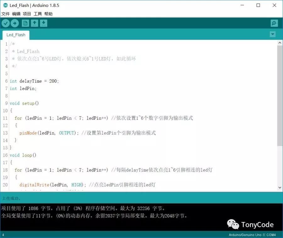
Program Upload
3. Experimental Phenomenon
The LEDs light up in sequence and then turn off in sequence, achieving a flowing effect.
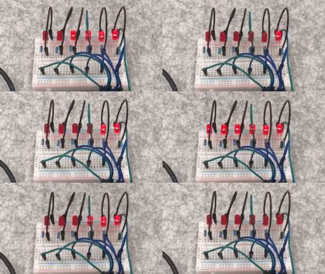
4. Program Analysis
In the setup section, the for loop sets pins 1 to 6 as output. In the loop section, two for loops light up LEDs 1 to 6 in sequence and turn off LEDs 6 to 1 in sequence, using the digitalWrite function.
The delay time is defined as 200; you can change it to control the flow speed. You can also try different lighting sequences by modifying the output order of the pins in the program.
