Abstract:
In response to the application demands for high-precision indoor autonomous navigation and positioning for pedestrians, a wearable human motion measurement device prototype integrating Arduino and the Xsens Awinda inertial measurement suite has been designed. This system is easy to wear and highly reliable, achieving synchronous measurement of dual-foot IMU information and foot distance, supporting wireless data transmission, remote storage, and analysis. The foot distance is continuously collected using a modified dual SRF10 ultrasonic ranging module, and combined with dual-foot inertial measurement data, a zero-velocity detection algorithm is used to derive walking gait patterns, which helps improve the accuracy of pedestrian inertial navigation positioning.
0 Introduction
Currently, autonomous navigation technology mainly relies on gait parameters in spatial and temporal dimensions, combined with biological characteristics for motion estimation and navigation positioning. One approach is to use sensors to measure the motion information of target parts and estimate motion characteristics by analyzing the signal characteristics of individuals while walking to determine step frequency and stride, integrating with heading measurement systems to obtain motion trajectories. However, this approach struggles to maintain a consistently high signal recognition rate due to the variable conditions encountered during actual walking. Another approach detects the zero-velocity state when the foot strikes the ground and uses the zero-velocity value as an observation for Kalman filtering to correct inertial navigation calculation errors. During walking, the ground contact time of both feet is relatively short, thus limiting this auxiliary effect. Furthermore, the zero-velocity state detection method has limited effectiveness in correcting gyroscope output errors, leading to significant deviations in walking trajectories over time.
Foot distance serves as a viable auxiliary navigation information. Current research in this area primarily divides into three directions: (1) calibrating the zero biases of two gyroscopes by tracking the distance between feet to constrain heading drift, using ultrasonic transceivers to determine foot distance [1]; (2) setting distance threshold constraints between the feet in algorithms to reduce heading errors [2-4]; (3) employing a single transmitter with multiple receivers, arranging multiple ultrasonic transceivers on both feet, to derive displacement and posture information from the time difference of receivers at different positions [5].
This paper takes this idea as a starting point and designs a wearable human motion measurement device prototype based on the Arduino development platform and Xsens Awinda MTw inertial sensors, achieving continuous and synchronous measurement of inertial information and foot distance information.
1 System Principle
The system uses a Micro-Electro-Mechanical Systems Inertial Measurement Unit (MEMS IMU) to measure the inertial data of the installation position during dual-foot movement. The design goals for the system platform meet four key points: (1) real-time measurement of the distance between feet under actual gait conditions, requiring accurate and stable data with sensitive feedback; (2) synchronized collection of information from all sensors; (3) automatic saving and processing of data; (4) portable and easy-to-use equipment. The hardware configuration of this system is illustrated in Figure 1.
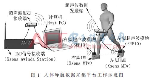
Two ultrasonic ranging modules are used to measure the distance between feet in any relative position. The ultrasonic data transmitter is responsible for ranging, wirelessly transmitting data to the ultrasonic data receiver at regular intervals. On the other hand, dual-foot inertial motion information is synchronously collected by the central control unit and sent to the computer. The computer combines control timing to obtain synchronized measurement information from each sensor.
2 System Hardware Design
2.1 Xsens MTw Awinda Suite
The Xsens MTw Awinda inertial measurement development suite includes a data central control unit, the Awinda Station, and multiple inertial sensors, MTw. The wireless Awinda Protocol based on IEEE 802.15.4 ensures data transmission to the Awinda Station. The synchronization error for data collection between each MTw unit is less than 10 μs. The internal sampling rate of the unit is 1,800 Hz. The Awinda Station includes four BNC synchronization I/O ports, two of which (Sync Out Line1 and Sync Out Line2) send control signals externally, with the control signal sourced from the internal data frame transition (Frame Transition) during data collection at the Awinda Station, indicating the moment each calculation cycle’s data frame transition ends.
MT Manager is the interactive control interface with MTw Awinda, using the built-in device message terminal (Device Message Terminal) to monitor inertial sensor information and set the wireless update rate for MTw and the synchronization signal trigger method for the Awinda Station.
From extensive literature, it is observed that most pedestrian navigation and positioning studies based on MEMS IMU use Xsens inertial motion sensors as the measurement platform.
2.2 Ranging Control Board
This device uses two Arduino development boards as core control modules. One serves as the ultrasonic data measurement and transmission end, responsible for collecting and sending ultrasonic data, and is carried on the person. The other acts as the ultrasonic data receiving end, synchronizing with the Awinda Station data.
2.3 Ranging Module
For the foot distance measurement scenario, this device employs ultrasonic ranging for measurement. The Devantech SRF10 has a ranging range of 3 cm to 6 m, with an accuracy of 1 cm, equipped with filtering and noise reduction functions, and a probe beam angle of 72°. It consists of three main components: the 400ST100 transmitting probe, the 400SR100 receiving probe, and the control circuit, with data communication via the I2C protocol. Different I2C addresses must be configured for SRF10s connected to the same I2C bus. Note the conversion of I2C addresses for Arduino and SRF10.
The ranging range and analog gain can be modified through the SRF10 registers, and appropriate parameters can reduce measurement errors. The larger the gain adjustment, the greater the sensitivity to receiving weak echoes.
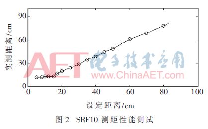
To adapt to real-time measurement of stride under normal gait conditions, the connection between the SRF10 transmitting probe and the control chip is extended, modified into a through-type ultrasonic module. Using laser ranging to calibrate measurement errors, the relationship between the measured distance and the actual distance is shown in Figure 2, indicating significant deviation in measured values when the actual distance is less than 20 cm.
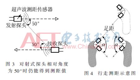
Directionality testing of the ultrasonic ranging module is shown in Figure 3. The modified SRF10 can achieve good ranging results when the relative angle between receiving and transmitting probes is within 50°. When installing two modified ranging modules, they are separated at a certain angle, as illustrated in Figure 4, with the angle between the probe heads denoted as α. Multiple preliminary tests were conducted, and when the stride range is 10 cm to 100 cm, adjusting angle α to 60° to 100° ensures normal data collection during walking. In this system platform, angle α is set to 90°.
The SCL and SDA in the I2C bus are both pulled high with pull-up resistors of 1.8 kΩ, with the SCL and SDA pins of SRF10 connected to the Arduino analog pins A5 and A4, respectively. The two SRF10s are connected in parallel, acting as slaves on the I2C bus. When the module sends ultrasonic data, the SDA of I2C is pulled high to ensure data transmission. Once the ranging result is obtained, the SRF10 responds again to the I2C bus, which is crucial for determining system latency and achieving synchronization.
2.4 Wireless Transmission Module
The nRF24L01 is a GFSK single-chip RF transceiver, operating in the 2.4~2.5 GHz ISM band, selecting channels and setting protocols via SPI interface, working in a master-slave manner in full-duplex mode, transmitting wireless data with synchronized clock beats, with fixed relative positions of signal symbols in the serial data stream. After powering on, the module is configured via the CE interface. This device uses the enhanced ShockBurstTM mode to control data acknowledgment and retransmission functions.
Two nRF24L01s are used as the transmitting and receiving ends, respectively, with two sets of ranging information collected in each cycle transmitted remotely, with the actual data size being 8 B.
2.5 Hardware Modification and Configuration of Target Device
The schematic diagram of the system hardware composition is shown in Figure 5.
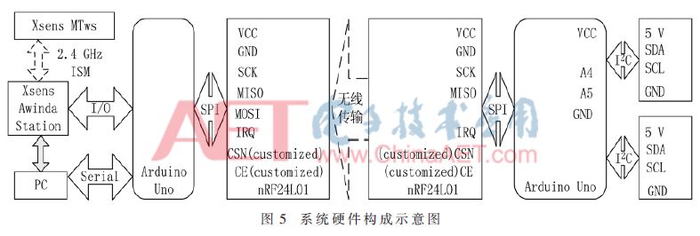
This device uses the TI TXS0108E bidirectional level shifting chip to ensure normal communication between modules, with a maximum data rate of 110 Mb/s (push-pull) and 1.2 Mb/s (open-drain). The A port of the chip tracks the power supply voltage at the VCCA pin, connecting to the 3.3 V voltage pin. The B port tracks the power supply voltage at the VCCB pin, connecting to the 5 V voltage pin. The output enable OE pin is set to high.
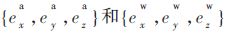
The hardware structure is divided into data collection, reception, and processing sections. The modified through-type SRF10 ultrasonic ranging module’s transmitting and receiving probes are installed on different Xsens MTws, with connecting wires bypassing the body and secured with Velcro, and the Xsens MTw is placed on the shoe upper. The self-designed mounting component allows adjustment of the angle between the transmitting and receiving probes. The coordinate system of the MTw and the device installation situation are illustrated in Figure 6, 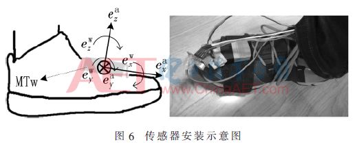 representing the three projection axes of the accelerometer and gyroscope outputs of the MTw.
3 Data Collection and Processing Flow
The main workflow of the system includes: wearing and installing the device, target motion and data collection, wireless data transmission, data fusion, and data storage and processing. Figure 7 illustrates the data collection and transmission process of the device. The collected motion data is wirelessly transmitted to the ultrasonic data receiving end and IMU data receiving end, with the computer simultaneously receiving timestamped ultrasonic ranging information and IMU inertial motion parameter information for synchronous processing and data calculation.
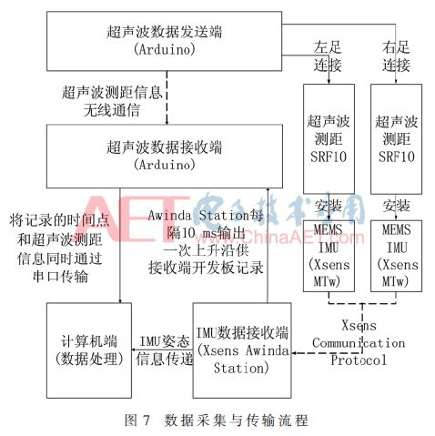
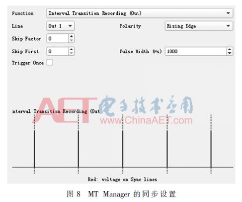
Figure 8 shows the synchronization signal trigger method settings of MT Manager. The Awinda Station sends a rising edge synchronization signal externally through Sync Out Line1, with a sending cycle of 10 ms, the same as the IMU data update cycle, and a signal pulse width of 1 ms. The Awinda Station starts data collection and calculation when instructed to begin recording, using the Interval Transition Recording synchronization method to ensure accurate data recording during the Awinda Station’s system clock.
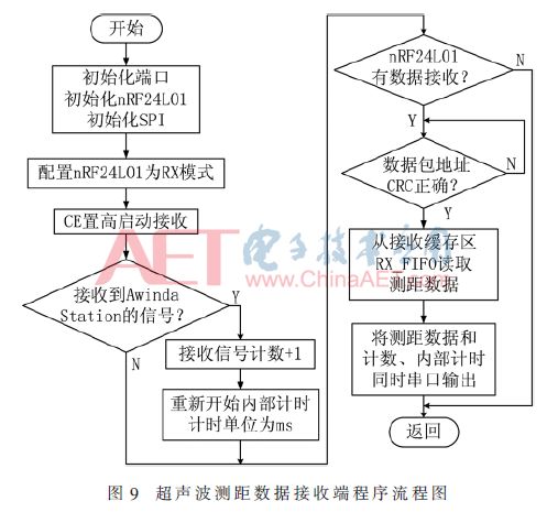
On one hand, the ultrasonic data receiving end Arduino counts the rising edge synchronization output signal of the Awinda Station for each frame using internal interrupts, achieving precise synchronization of collection time with a synchronization accuracy of 1 ms. Once two ultrasonic ranging data points are received, the ranging values and the current count results are output simultaneously to obtain the raw data. The Arduino program flowchart for the ultrasonic data receiving end is shown in Figure 9. The inertial data update frequency for the two wireless MTw inertial sensors is 100 Hz. On the other hand, the Awinda Station outputs the collected inertial data to the computer, with the file containing the output from each MTw sensor (Sensor Component Readout).
The SRF10 collects foot distance data in ms, converting the data to distance measurement values during processing. Since simultaneous ranging from two SRF10s can cause interference, the ranging time interval is set to 20 ms, with both ranging data transmitted to the receiving end simultaneously after each ranging, with the ranging cycle for SRF10 and ultrasonic data transmission both set at 50 ms.
Regarding the selection of ultrasonic ranging frequency, the following points are considered: (1) A typical complete gait cycle for an average person walking at a normal speed is about 1.2 s to 1.8 s, with the airborne phase time of any foot approximately 31.8% [6]; (2) Based on the stride length during various movements (e.g., walking, running), the module’s ranging range is set to 2 m, requiring around 5.8 ms for the module to process data, thus the SRF10 ultrasonic ranging sampling cycle cannot be less than this duration, adjusting the analog gain and module detection frequency and ranging parameters accordingly; (3) The output frequency of the ultrasonic ranging module and the output frequency of the Awinda Station are set to be integer multiples to ensure data transfer synchronization.
At the ultrasonic data transmission end, the SRF10 requires a delay after collecting data (set to 20 ms in the program) before reading measurement data from the register. The pulse signal when the ultrasonic probe begins operation and the pulse signal received by the Arduino at the ultrasonic data receiving end are detected via an oscilloscope, revealing that the average total time consumed for the device data transmission process is 21.5 ms, with the additional 1.5 ms primarily spent on wireless transmission. Based on the data, the specific moments for the SRF10’s activation and ranging are determined, allowing for the combination of ranging data with IMU data to complete synchronized collection.
The device synchronization process is based on the internal clock of the Awinda Station, and the ultrasonic ranging cycle can be adjusted to a minimum of 30 ms.
4 Device Data Collection and Processing
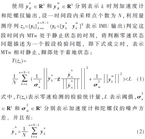
Using two SRF10s to measure real-time foot distance under normal human gait conditions, due to the beam angle of the ultrasonic probe, the module installation method allows obtaining two measurement values simultaneously. The approach is to combine the inertial motion parameters collected by the Xsens MTw and apply the zero-velocity detection algorithm [7] to determine the periods when both feet are relatively stationary on the ground, thus deriving the stepping motion patterns.
Using the above zero-velocity detection algorithm, data collection tests with this wearable device were conducted while walking in a straight line at a constant speed (approximately 5 km/h) for a duration of 10 seconds, with the results of human motion data measurement illustrated in Figure 10.
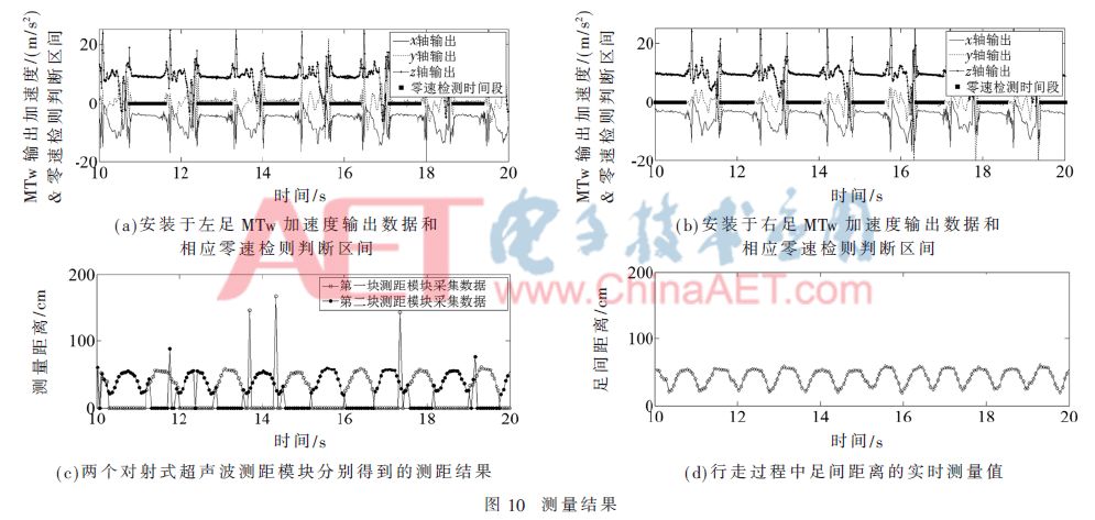
Figure 10(a) and Figure 10(b) show the three-axis output of the accelerometer measured by the left foot MTw and right foot MTw, respectively, and the states determined by the zero-velocity detection algorithm indicating when the foot is in the ground contact phase, thereby obtaining the periodic gait of foot contact, landing, lifting, and swinging. Figure 10(c) presents the ranging values obtained from the two ultrasonic ranging modules, noting that due to the characteristics of echo ranging, some outlier points exist in the actual measurement values. The ranging results from the two modules are selected and processed based on gait information as follows: (1) The direction of each step is determined according to the output from the inertial sensors; (2) Taking the walking direction as forward, under normal conditions, one foot’s position at the moment of ground contact is located slightly in front of the other foot; based on the previous module installation conditions, the ranging value from the module that matches this angular measurement position is selected; (3) This operation is repeated for each step, combining the relative position change patterns of both feet to ultimately obtain real-time measurements of the foot distance while filtering out some outlier points, resulting in the final measurement values shown in Figure 10(d).
5 Conclusion
This system integrates inertial measurement units and ultrasonic ranging sensors to directly and in real-time measure the distance between feet during pedestrian motion, achieving synchronized collection of pedestrian navigation data, advancing research that uses stride length as a new constraint condition for pedestrian navigation, and utilizing wireless communication modules for remote data storage and processing without needing to carry a computing terminal, making it lightweight and portable, with stable and reliable data collection that meets the requirements for wearable human motion measurement. Future work based on this hardware platform includes: (1) Using more ultrasonic ranging transceiver modules to measure foot distance under more complex angle conditions for various gait scenarios; (2) Aiming for overall modularization of the platform to provide ideas for enhancing the functionality of navigation shoes, with the data processing portion being portable to other device terminals based on actual usage needs.
References
[1] LAVERNE M, GEORGE M, LORD D, et al. Experimental validation of foot to foot range measurements in pedestrian tracking[C]. Proceedings of the 24th International Technical Meeting of The Satellite Division of the Institute of Navigation, Portland, OR, September, 2011: 1386-1393.
[2] GIRISHA R, PRATEEK G V, HARI K, et al. Fusing the navigation information of dual foot-mounted zero-velocity-update-aided inertial navigation systems[C]. International Conference on Signal Processing and Communications. IEEE, 2014: 1-6.
[3] PRATEEK G V, GIRISHA R, HARI K V S, et al. Data fusion of dual foot-mounted INS to reduce the systematic heading drift[C]. 4th International Conference on Intelligent Systems, Modelling and Simulation. IEEE, 2013: 208-213.
[4] SKOG I, NILSSON J O, ZACHARIAH D, et al. Fusing the information from two navigation systems using an upper bound on their maximum spatial separation[C]. International Conference on Indoor Positioning and Indoor Navigation. IEEE, 2012, 68(2): 1-5.
[5] SUPINO R, HORNING R D. Method of personal navigation using stride vectoring: US, US8078401[P], 2011-12-13.
[6] GODHA S, LACHAPELLE G. Foot mounted inertial system for pedestrian navigation[J]. Measurement Science and Technology, 2008, 19(7): 075202.
[7] SKOG I, HANDEL P, NILSSON J O, et al. Zero-velocity detection—an algorithm evaluation[J]. IEEE Transactions on Biomedical Engineering, 2010, 57(11): 2657-2666.
Author Information:
Zhou Luyang1, 2, 3, Hu Yigong2, Wu Yuanxin2, 3
(1. School of Aerospace, Central South University, Changsha, Hunan 410083; 2. School of Electronic Information and Electrical Engineering, Shanghai Jiao Tong University, Shanghai 200240;
3. Key Laboratory of Beidou Navigation and Location Service, Shanghai 200240)