To use the Cortex-M microcontroller in general applications, one needs to understand several aspects, including the programming model, how exceptions (such as interrupts) are handled, memory mapping, how to use peripherals, and how to utilize the software driver libraries provided by the microcontroller vendor.
First, let’s take a look at the programming model of the processor, which involves operating modes, register groups, and special registers.
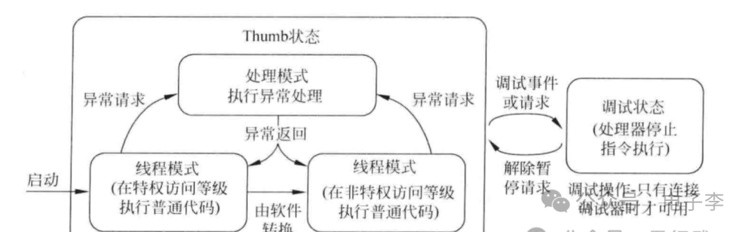
The Cortex-M3 processor has two operating states: Thumb state and Debug state.
In Thumb state, the processor executes 16-bit and 32-bit halfword-aligned Thumb-2 instructions.
Note: The Cortex-M3 processor does not support ARM instructions, so there is no ARM state.
In Debug state, the processor stops executing and enters this state for debugging.
Handler mode: Executes interrupt service routines (ISRs) and other exception handling. In handler mode, the processor always has a privileged access level.
Thread mode: When executing normal application code, the processor can be in either privileged or unprivileged access level. The actual access level is controlled by the special register CONTROL.
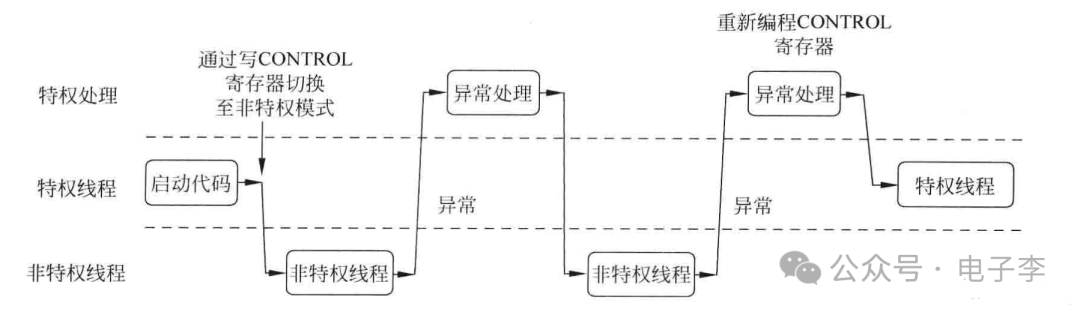
As shown in Figure 1.1, software can switch the processor from privileged thread mode to unprivileged thread mode, but cannot switch itself from unprivileged thread mode to privileged mode; if such a switch is necessary, it must be done using the exception mechanism.
As shown in Figure 1.1, software can switch the processor from privileged thread mode to unprivileged thread mode, but cannot switch itself from unprivileged thread mode to privileged mode; if such a switch is necessary, it must be done using the exception mechanism.
The Cortex-M3 processor supports the following data types: word, halfword, and byte.
Halfword is 16 bits long and must be accessed in a 2-byte aligned manner.
Word is 32 bits long and must be accessed in a 4-byte aligned manner.
Registers are temporary storage areas within the computer processor for storing data and program states, akin to the processor’s “thinking area.” Thus, registers can be viewed as the processor’s “brain,” providing support and helping the computer execute instructions.
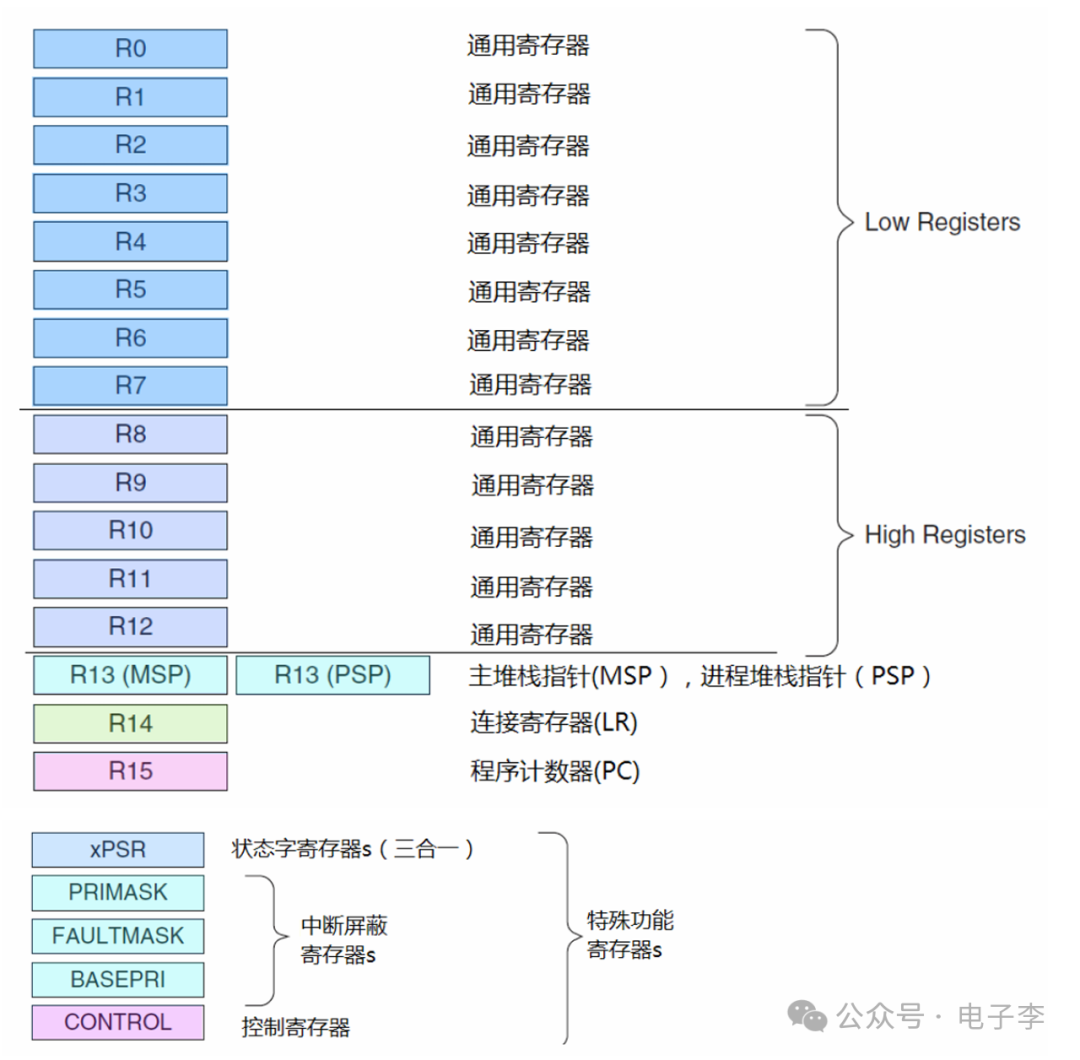
The Cortex-M3 processor has a word length of 32 bits, and its registers are also 32 bits. All of its 32-bit registers are shown in the figure.
1). General-purpose registers R0~R12
R0~R12 are 32-bit general-purpose registers that have no special defined purpose structurally and are usually used for data operations in practical programming. These 13 general-purpose registers are divided into two categories:
R0~R7, also known as low registers, can be accessed by all instructions. It is important to note that their initial values after reset are unpredictable.
R8~R12, also known as high registers, can only be accessed by 32-bit instructions. Similar to low registers R0~R7, their initial values after reset are unpredictable.
2). Stack Pointer Register R13
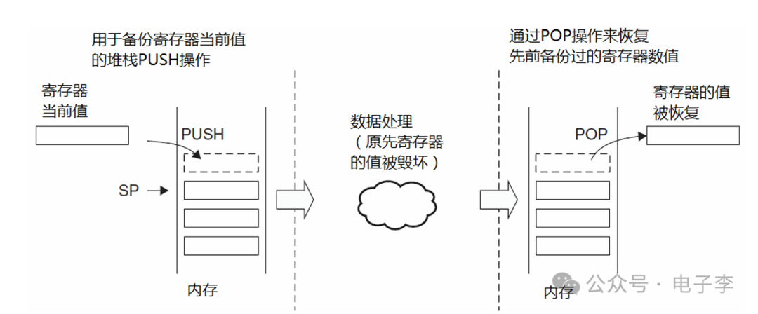
R13, also written as SP (Stack Pointer), is used as the stack pointer; almost every processor has a similar register for accessing the stack. The stack is a special storage area made up of a contiguous memory block and a stack pointer. Stack operations involve reading and writing to memory, but the stack is a memory area with special properties, and its access address can only be provided by the stack pointer, which is the stack pointer register SP.
The stack is typically used to temporarily store data that is about to be modified or is easy to modify (such as CPU registers) so that it can be restored later. For example, before data processing or exception handling, the values of the CPU registers are saved (pushed onto the stack), and after data processing or exception handling is completed, these previously protected values (CPU register values) are restored (popped from the stack).
Main Stack Pointer (MSP), or written as SP_main, is the default stack pointer after reset, primarily used by the operating system kernel, exception service routines (including interrupt service functions), and all user applications that require privileged access.
Process Stack Pointer (PSP), or written as SP_process, is mainly used by regular user applications. Although the Cortex-M3 has two SPs, only one can be seen or used at a time; this is known as banked registers. When referencing R13 (or SP), it refers to the one currently in use, while the other must be accessed with special instructions (MRS/MSR instructions).
R14, also written as LR (Link Register), is the link register for subroutines, usually used to save the return address when calling a subroutine. For example, when executing the BL (Branch and Link) instruction, the processor automatically writes the return address into LR.
int main() { printf("hello world!!\n"); return 0; } // After assembly: main: bl printf // Call subroutine, assign pc value to lr // Return from subroutine
R15, also written as PC (Program Counter), is used to store the address of the next instruction to be executed. This is a very important register; by modifying the value of PC, one can change the program flow and achieve jumps (without updating LR).
For example, in the previous example, at the end of the subroutine, using the instruction “MOV PC, LR” loads the return address stored in LR into PC, thereby returning from the subroutine.
5). Special Function Register Group
Special function registers have predefined functions and must be accessed via dedicated instructions (MSR/MRS) to access the special function registers of the Cortex-M3.
Program Status Register Group xPSR.
Interrupt Mask Register Group (FAULTMASK, PRIMASK, and BASEPRI).
Control Register CONTROL.
6). Program Status Register Group xPSR (Program State Register)
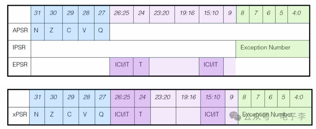
The program status register is internally divided into three sub-status registers: Application PSR (APSR), Interrupt PSR (IPSR), and Execution PSR (EPSR).
Through the MRS/MSR instructions, these three PSRs can be accessed individually or in combination (two or three combinations are possible). When accessed in a three-in-one manner, the name xPSR or PSR should be used, as shown in the figure.
The bit allocation and significance of the program status register are as follows:
N (Negative): Negative or less than flag (1 indicates the result is negative or less, 0 indicates the result is positive or greater).
Z (Zero): Zero flag (1 indicates the result is zero, 0 indicates the result is not zero).
C (Carry/Borrow): Carry/Borrow flag (1 indicates the result has a carry or borrow, 0 indicates the result has no carry or borrow).
V (Overflow): Overflow flag (1 indicates the result has overflowed, 0 indicates the result has not overflowed).
ICI/IT (Interrupt Continuable Instruction/IF-THEN): Interrupt-continuable instruction flag, execution state flag for IF-THEN instructions.
T: Thumb state flag (always 1; if an attempt is made to clear this bit, it will cause a fault exception).
Exception Number: The current exception or interrupt number being processed (2 indicates NMI, 11 indicates SVCall, 16 indicates INTISR[0], 17 indicates INTISR[1], …, 255 indicates INTISR[239]).
7). Interrupt Mask Register Group (FAULTMASK, PRIMASK, and BASEPRI)
The interrupt mask register group is mainly used to control the enabling and disabling of exceptions, including the three registers FAULTMASK, PRIMASK, and BASEPRI.
The FAULTMASK register is a 1-bit register. Setting it to 1 disables all other exceptions except for NMI (Non-Masked Interrupt).
Its default value is 0, indicating that no exceptions are disabled.
The FAULTMASK register is often used by the operating system when handling task crashes. When a task crashes, it may cause a series of different errors. Once the CPU begins to clean up the task, the FAULTMASK register should be set to 1 to temporarily disable hard fault exceptions, thereby preventing the cleanup process from being interrupted by other error exceptions caused by the crashing task. After the cleanup is complete, the FAULTMASK register can be cleared to re-enable exceptions.
The PRIMASK register is also a 1-bit register. Setting it to 1 disables all maskable exceptions, leaving only NMI and hard faults responsive. Its default value is also 0, indicating that no interrupts are disabled.
The BASEPRI register can have up to 9 bits (the specific number depends on the number of priority bits). It defines the threshold for masked priorities. When it is set to a certain value, all interrupts with priority numbers greater than or equal to this value are disabled (the higher the priority number, the lower the priority). Its default value is also 0, indicating that no interrupts are disabled. The BASEPRI register and PRIMASK register are often used to temporarily disable some interrupts for time-sensitive tasks.
8). Control Register CONTROL
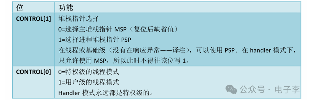
The Control Register CONTROL is a 2-bit register, where one bit defines the privilege level, and the other bit selects which stack pointer is currently in use.
Disclaimer: The information is sourced from Luffy Academy. This account maintains a neutral stance on all original and reprinted articles’ statements and viewpoints, and the articles are provided solely for readers’ learning and exchange. The copyrights of the articles and images belong to the original authors. If there is any infringement, please contact for deletion.