Hello everyone, I am Pi Zi Heng, a serious technical person. Today, I will share with you the Cortex-M System Interrupt Latency and Measurement Methods.
In the embedded field, real-time performance is a concept we often emphasize. Here, real-time performance mainly emphasizes whether the system can respond within a specified time frame when external events occur. The smaller this time threshold, the higher the system’s real-time performance. Of course, there are hard and soft real-time requirements. Hard real-time requires that the response must be completed within the set time threshold, while soft real-time only needs to complete the response as quickly as possible based on task priority.
Whether in an RTOS environment or a bare-metal environment, the fundamental assurance of the system’s real-time capability actually comes from the interrupt response capability of the MCU core. An important indicator of interrupt response capability is called interrupt latency time. Today, we will discuss the interrupt latency and measurement methods of the Cortex-M core:
1. What is System Interrupt Latency?
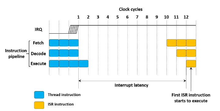
Interrupt latency refers to the interval from when the interrupt request (IRQ) signal is triggered until the kernel begins executing the first instruction of the interrupt service routine (ISR). As shown in the figure below, the 11 cycles within the arrow range represent the interrupt latency time. This concept is detailed in a blog by ARM expert Joseph Yiu titled “Introduction to Cortex-M Core System Interrupt Latency”.

Why does interrupt latency occur? This is unavoidable. When the kernel is executing the main thread code and an interrupt event occurs, the corresponding IRQ signal in the NVIC is triggered. After the kernel receives the NVIC notification, it saves the context (to return to the interrupted main thread after the ISR processing is complete) and then retrieves the corresponding ISR from the interrupt vector table to execute. This series of actions takes time.
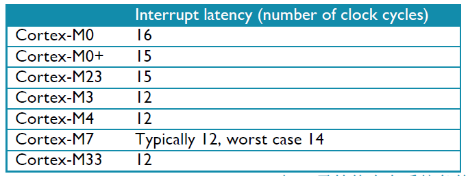
As the Cortex-M family has developed, there are now several cores such as M0/M0+/M1/M3/M4/M7/M23/M33/M35P/M55, each with different interrupt latency times, as shown in the table below. Note that the values in the table are in clock cycles of the core and are results under zero-wait memory system conditions (i.e., the code is linked in zero-wait memory).
Note1: Generally, SRAM that operates at the same frequency as the MCU core is considered standard zero-wait memory. Note2: Many microcontrollers with operating frequencies above 100MHz are paired with very slow Flash memory (for example, 30 – 50MHz). Although hardware acceleration can be used to improve performance, interrupt latency is still affected by the wait states of the Flash memory system.

2. How to Measure System Interrupt Latency?
There are many methods to measure the interrupt latency of Cortex-M. Any MCU peripheral module with interrupts can be used to measure interrupt latency. The interrupt latency time of Cortex-M is basically unrelated to the specific type of peripheral module that triggers the interrupt (it may be slightly affected by the synchronization cycle of the peripheral’s interrupt signal).
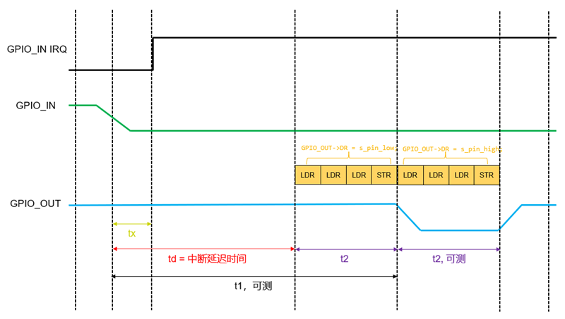
Using the GPIO module to measure the interrupt latency of Cortex-M is the simplest method. Choose two GPIOs, one configured as input (GPIO_IN) and the other as pull-up output (GPIO_OUT, initially set to high). Enable the edge interrupt for GPIO_IN (for example, falling edge), and in the GPIO_IN edge interrupt ISR, toggle GPIO_OUT twice, then use an oscilloscope to measure the interval between the two GPIO signal edges to obtain the interrupt latency time.
uint32_t s_pin_low  = 0x0;
uint32_t s_pin_high = 0x1;

void GPIO_IN_IRQHandler(void)
{
    GPIO_OUT->DR = s_pin_low;
    GPIO_OUT->DR = s_pin_high;

    ClearInterruptFlag(GPIO_IN);
    __DSB();
}
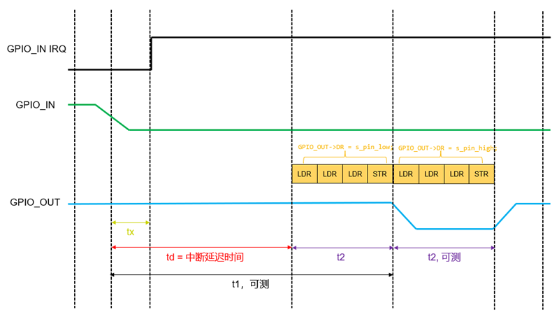
It is important to note that in the above pseudo code for GPIO_IN_IRQHandler, we toggled GPIO_OUT twice, which is necessary. If we randomly choose a CM7 chip to compile (in IAR environment, without optimization), we can see the following assembly code. Each toggle actually consists of four instructions. The first edge of GPIO_OUT, which serves as our timing reference, occurs after the first toggle code is executed in the ISR, while the interrupt latency does not include the execution time of the first toggle code. Due to complex situations such as instruction pipeline optimization, we will not theoretically calculate the actual clock cycles consumed by the four instructions but will toggle GPIO_OUT once more, measuring the low time of GPIO_OUT, which is considered the execution time of these four instructions.

Thus, the final interrupt latency time td = t1 – t2, where t1 and t2 are times we can measure. Additionally, the td time includes tx, which is the time from the I/O signal transition to the internal IRQ trigger of the chip. This time is the synchronization time required by the chip system, varies by chip design, and should not be counted in the system interrupt latency. However, since this time cannot be measured, it is included in the interrupt latency, which is a small error.
In the next article, we will actually measure the interrupt latency on a Cortex-M chip using this method, so stay tuned.

That concludes the introduction to the Cortex-M system interrupt latency and its measurement methods. Where’s the applause~~~