Hello everyone, I am Pi Zi Heng, a serious technical enthusiast. Today, I will introduce the ARM Cortex-M stack mechanism.
This article is a technical document I wrote before 2016, and I have spent some time reorganizing the format. Previously, I discussed the “Principle of Stack in Embedded Systems”; this article serves as an engineering practice of stack principles, specifically its application on ARM Cortex-M. The ARM Cortex-M family has evolved through many generations, and we will take the simplest Cortex-M0 as an example to discuss the stack mechanism:
1. Basic Rules
1.1 R13 / SP Register
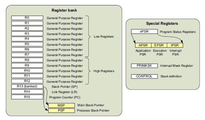
R0-R12 are general-purpose registers, and R13 is the system stack pointer (sp), which is used to access the stack, i.e., the system’s RAM area. The Cortex-M0 uses two stack pointers: the Main Stack Pointer (MSP) and the Process Stack Pointer (PSP). R13 can only point to one at any given time, with the default being MSP, which can be changed via the Control Register (CONTROL).
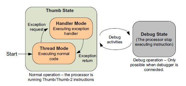
MSP is designated as the sp after the system reset (i.e., when it is in Handler Mode), used for handling exception interrupts. After the Reset_Handler ends, the CPU enters normal operation state (i.e., Thread Mode), and only in this state can PSP be used, although MSP can also be used. If a hard interrupt occurs afterward, it enters Handler Mode, and upon the end of the hardware interrupt, it returns to Thread Mode.
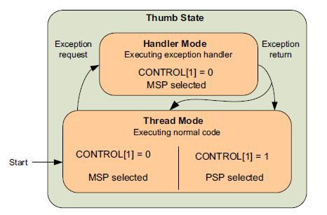
The selection of MSP and PSP is configured via the CONTROL register, which can only be set in Thread Mode. Generally, there is no need to use PSP unless an OS is present, where MSP is used for the OS kernel’s sp, and PSP is used for thread-level app’s sp; these two sp must be strictly separated. In the compiler, the stack can be accessed via r13 (R13) or sp (SP) (specifically, whether it is MSP or PSP is determined by the current environment); MSP and PSP can also be accessed through designated MRS and MSR instructions.
1.2 Stack Structure
Stack structure without OS:
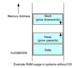
Stack structure with OS:
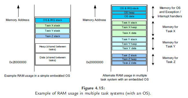
1.3 Stack Operations
In Cortex-M0, the stack grows towards lower address directions, implementing a full stack mechanism. Stack operations are performed using PUSH and POP commands.
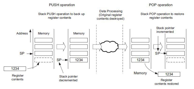
The stack is generally placed in the higher memory area of the ARM’s RAM; for instance, in a certain MCU, the RAM address is from 0x20000000 to 0x20007fff, totaling 32KByte. If the stack size is set to 4KByte, its address is typically from 0x20007000 to 0x20007fff, where 0x20007000 is the absolute stack top, and 0x20007ffc is the absolute stack bottom, with sp always pointing to the relative stack top. The first PUSH data is stored at the absolute stack bottom (at this point, the absolute stack bottom is also the relative stack top). In fact, besides the POP instruction that can retrieve data from the stack top, the MOV instruction can also retrieve data from any position, but it does not affect the stack structure (i.e., it does not affect its sp). Since ARM registers are all 32 bits, both PUSH and POP instructions access 32 bits, thus the sp pointer is always at least 4-byte aligned (the lowest 2 bits are always 0). Sometimes the compiler may also allocate an 8-byte aligned stack, as double floating-point types require 8 bytes; for convenience, the stack is set to 8-byte alignment.
2. Stack Push Order
The push order varies based on the compiler, processor system, and OS; there is no strict specification in C language regarding the push order. This section mainly discusses the push order of ARM Cortex-M series processors under specified compilers.
2.1 General Function Call (General)
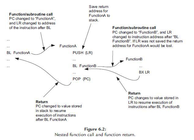
The above image shows the operations of sp during the nested calls of a general function (with no parameters, local variables, or return values). When executing the BL FunctionA instruction, LR records the next sequential instruction after BL FunctionA; the first operation executed upon entering FunctionA is PUSH {LR}, which pushes the next sequential instruction onto the stack, and only then does the function body of FunctionA begin execution. After the function body execution is completed, the POP {PC} instruction is used to pop the stack top data into the PC, thus returning to continue executing the next sequential instruction of BL FunctionA.
2.2 Extreme Function Call (Platform Dependent)
Consider an extreme case to elaborate on the push order, where the function has more than four parameters, defines multiple local variables within the function body, and has a return value. This situation is quite special, and I have specifically conducted an experiment on IAR; see today’s follow-up post (it’s a long image, and understanding it requires a certain foundation in assembly):
Thus, the introduction to the ARM Cortex-M stack mechanism is complete; where’s the applause~~~