The channel interface is used for transmitting events between different Coresight components. It is implemented using two components:
-
CTM: Cross Trigger Matrix, which receives CTI channel signals and broadcasts them to other CTIs.
-
CTI: Cross Trigger Interface, which receives trigger signals, sends trigger signals, receives channel signals, and sends channel signals.
Typical applications of the channel interface.
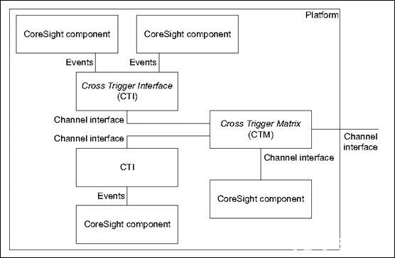
Each Coresight component is connected to the corresponding CTI, allowing the CTI to collect trigger signals from the components or send trigger signals to the components.
The CTI sends the received trigger signals to the channel interface or receives trigger signals from the channel interface to send to the connected Coresight components.
All CTI channel interfaces are connected to the CTM, enabling each CTI to transmit trigger signals to each other through the CTM.
1. Channel Interface Signals
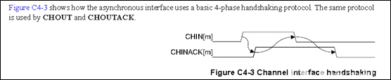
The signals transmitted by the channel interface use a handshake mechanism for signal transmission. Since different CTIs operate at different clock rates, a handshake mechanism is required to ensure that events can be transmitted between different CTIs.
There are a total of four signals, with the direction relative to the CTI.
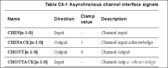
The clamp value refers to the fixed value on the output when the device is powered down or disabled.
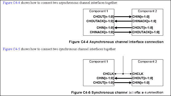
Below is the timing diagram:
There are two connection methods: asynchronous and synchronous.
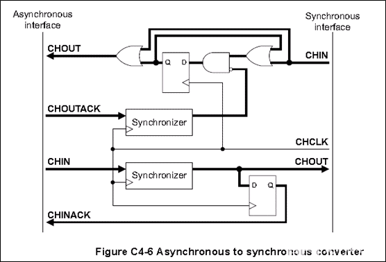
Conversion between synchronous and asynchronous interfaces.
2. CTI
CTI has input triggers and output triggers. ARM defines these triggers:
Below are the output triggers:
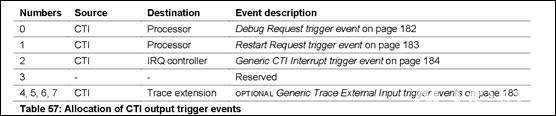
trigger0: Connected to CPU, debug request signal. When this signal is valid, it indicates that the connected CPU enters debug state.
trigger1: Connected to CPU, restart request signal. When this signal is valid, it allows the connected PE to exit debug state.
trigger2: Connected to the interrupt controller, CTI interrupt. When this signal is valid, it sends the CTIIRQ signal to the interrupt controller to generate an interrupt.
Below are the input triggers:
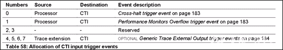
trigger0: Connected to CPU, cross-halt trigger. When this signal is valid, it indicates that the connected PE enters debug state.
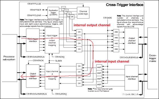
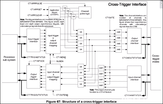
Below is the internal structure of the CTI:
The left side of the CTI connects to the CPU, with two channels: one receives input triggers sent from the CPU, and the other sends output triggers to the CPU.
The right side of the CTI connects to the CTM, used for sending output channels and receiving input channels.
There are four types of CTI interface signals:
-
Input triggers: Trigger event inputs from the processor to the CTI. Trigger signals are sent from the PE to the CTI.
-
Output triggers: Trigger event outputs from the CTI to the processor. Trigger signals are sent from the CTI to the PE.
-
Input channels: Channel event inputs from the CTM (cross-trigger matrix) to the CTI. Channel signals are sent from the CTM to the CTI.
-
Output channels: Channel event outputs from the CTI to the CTM. Channel signals are sent from the CTI to the CTM.
Input trigger & output channel mapping: Based on the CTIINEN signal, the input trigger is connected to the specified output channel.
Input channel & output trigger mapping: Based on the CTIOUTEN signal, the input channel is connected to the specified output trigger.
For each output trigger, there is a separate register corresponding to it. For example, CTIOUTEN0 corresponds to output trigger0. By controlling this register, the specified input channel can be connected to output trigger0, allowing the trigger from the specified input channel to be transmitted to output trigger0.
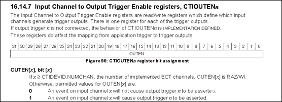
The register is 32 bits, indicating that one can select from 32 input channels (the maximum number of output triggers for ARMv8 is 32). If the value of the register is 0x1, it indicates that output trigger0 is connected to input channel0; if the value is 0x4, it indicates that output trigger0 is connected to channel2.
For the CTI, it can receive three types of input signals: one is the core’s trigger inputs, another is the CTM’s input channel, and the third is the trigger signals generated by the external debugger accessing the registers via APB.
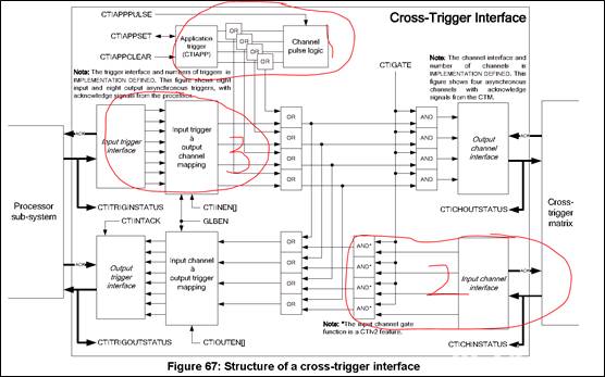
There are three sources in total:
-
CTI internal logic CTIAPP, which can be accessed externally via the APB bus.
-
External CTM.
-
Input triggers sent from the CPU.
2.1 For the CTIAPP of Internal Logic
This part provides several registers that can be accessed externally via the APB bus to control the generation and cancellation of trigger signals.
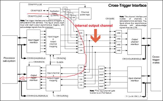
The external debugger can control these registers to enable the corresponding internal output channels, and then control CTIOUTEN[], allowing the data from the internal output channel to be output to the specified output trigger.
Below is the trigger flow diagram.
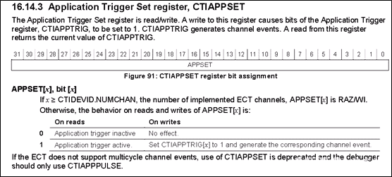
ARMv8 defines three registers: CTIAPPSET, CTIAPPCLEAR, CTIAPPPULSE.
-
CTIAPPSET: Generates a channel event on the specified internal channel.
-
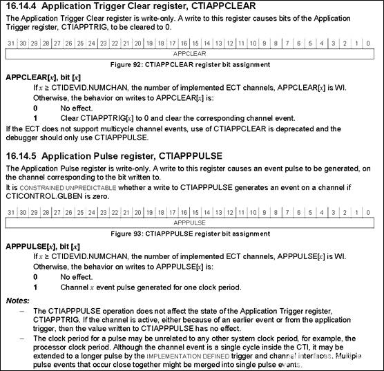
CTIAPPCLEAR: Cancels the channel event on the specified internal channel.
-
CTIAPPPULSE: Generates a channel event on the specified internal channel that lasts for only one cycle.
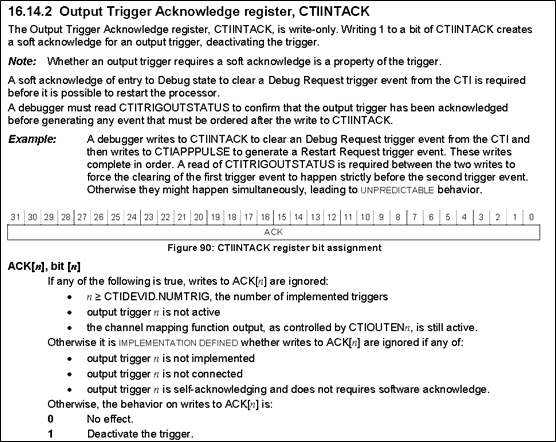
CTIINTACK. This register is used to invalidate the signals on the output trigger. For example, if the current output trigger0 is valid, indicating a debug request, writing 0x1 to this register will invalidate it.
Each bit of the register corresponds to the respective output trigger.
-
CTIINTACK[0] corresponds to output trigger0.
-
CTIINTACK[1] corresponds to output trigger1.
-
CTIINTACK[2] corresponds to output trigger2.
-
…
-
CTIINTACK[31] corresponds to output trigger31.
Since ARMv8 specifies that the maximum number of output triggers is 32, a 32-bit register can represent all of them.
2.2 External CTM
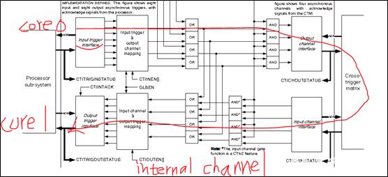
The input trigger signal sent from core0 reaches the output trigger signals of all other cores through the output channel and then through the CTM.
The input trigger signal sent from core0 goes through the input trigger mux (selected by CTINEN[]) to the corresponding internal input channel. If the subsequent AND gate is enabled (i.e., the CTIGATE signal is valid), the trigger signal on the channel will be transmitted to the CTM through the output channel interface.
The CTM sends the trigger to the external input channel of the CTI of other cores (here core1). If the AND gate of the other core is enabled (i.e., the CTIGATE signal is valid), it will be transmitted to the internal input channel of the CTI and sent to core1 through the output trigger mux (selected by CTIOUTEN[]).
This is the mechanism for transmitting trigger signals between different cores of the CTI. Through this mechanism, one core can send trigger signals to another core, allowing control over entering and exiting debug states.
2.3 CPU Sent Input Trigger
The input trigger from the CPU is received and sent to the internal input channel through the internal output channel, and then sent to the output trigger.