Previously, due to the robot dog project, I had been using the Xiaomi micro motor, but I struggled to find a detailed tutorial, encountering many pitfalls while learning to control the motor. Today, we will implement the control of the Xiaomi micro motor step by step using buttons. This article will analyze the Xiaomi motor driver library and briefly introduce relevant CAN communication knowledge. It is recommended to read the Xiaomi motor manual before this article, which can be found easily through a search engine.
1. Prerequisite Knowledge
The Xiaomi micro motor is a type of servo motor. So, what is a servo motor?
The most significant feature of a servo motor is the servo mechanism.
The servo mechanism is an automatic control system that follows the changes in the control quantities such as the object’s position, orientation, and posture according to a target (or set value). The English term “servo” is derived from the Latin word “servus,” meaning “slave,” which refers to the control that acts according to instructions.
For the Xiaomi motor, there are various control modes, and the flowchart of its operation mode is as follows:
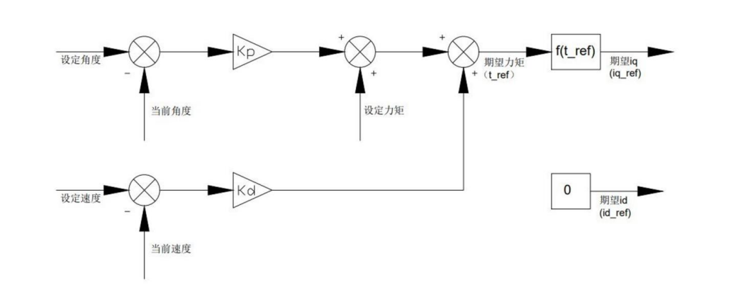
However, for us, we can treat the Xiaomi micro motor as a black box. As long as we power it and send it commands, it will rotate according to the commands. We do not need to concern ourselves with the motor’s current, voltage, or related control algorithms, as these have already been packaged within the servo system.
What is CAN communication? How does CAN communication work?
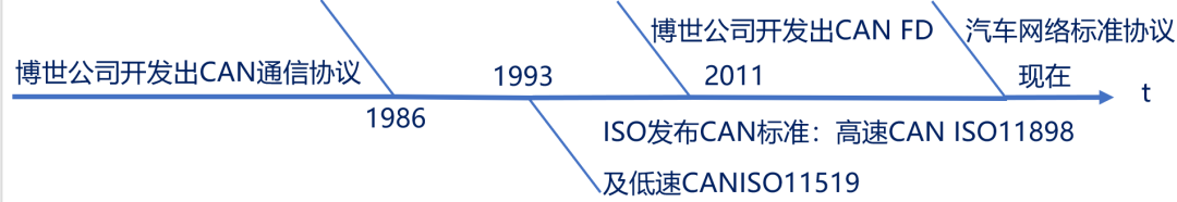
CAN (Controller Area Network) is an ISO standardized serial communication protocol.
It was developed to meet the automotive industry’s needs for “reducing the number of wiring harnesses” and “high-speed communication of large amounts of data through multiple LANs.”
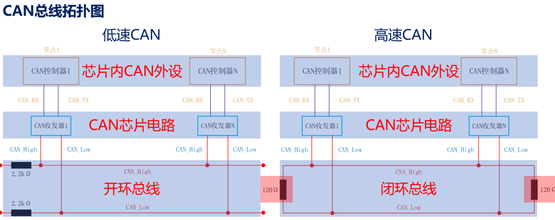
Low-speed CAN (ISO11519) communication rate is 10~125Kbps, with a bus length of up to 1000 meters.
High-speed CAN (ISO11898) communication rate is 125Kbps~1Mbps, with a bus length of ≤40 meters.
CAN FD communication rate can reach 5Mbps and is compatible with classic CAN, following ISO 11898-1 for data transmission and reception.
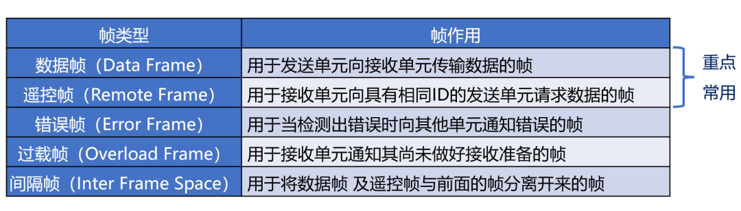
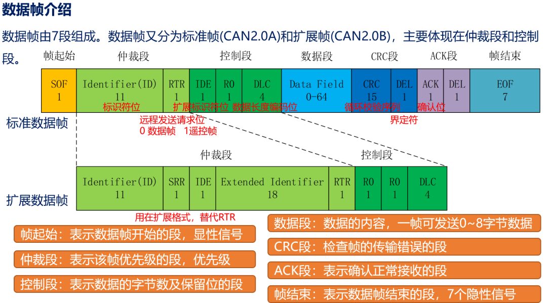
CAN bus communication occurs in the form of “frames.” The CAN protocol defines five types of frames: data frame, remote frame, error frame, overload frame, and intermission frame, with the data frame being the most commonly used. The data frame can be divided into standard frame and extended frame.
This information is enough for us to understand; we only need to know that the Xiaomi micro motor uses: high-speed CAN, baud rate 1M, extended frame format!
2. Xiaomi Motor Communication Protocol
The motor communication is via the CAN 2.0 communication interface, with a baud rate of 1Mbps, using the extended frame format, as shown below:
The supported control modes of the motor include: operation mode: specifying five parameters for motor operation; current mode: specifying the Iq current for the motor; speed mode: specifying the running speed for the motor; position mode: specifying the position for the motor, which will run to that specified position;
Wow! The data frame for CAN communication is so complex, and this communication protocol is not simple. How do we understand it?
Let’s first take a look at a screenshot of the software.
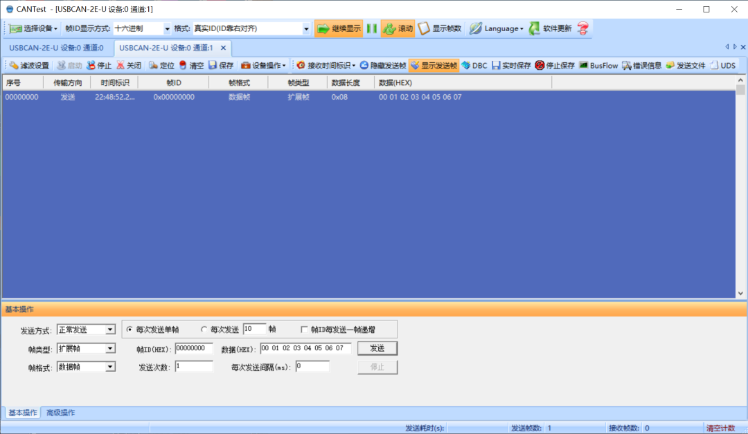
In the operation area below, do you notice that the only things we need to focus on and set are the ID and data?
Because in the CAN communication data frame, the only things we can change or convey information are the ID and data.
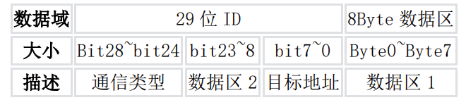
The Xiaomi communication protocol works the same way: by setting the ID and data (in hexadecimal format) and then sending it to the motor, we can control the motor.
Here, we take obtaining motor information as an example.
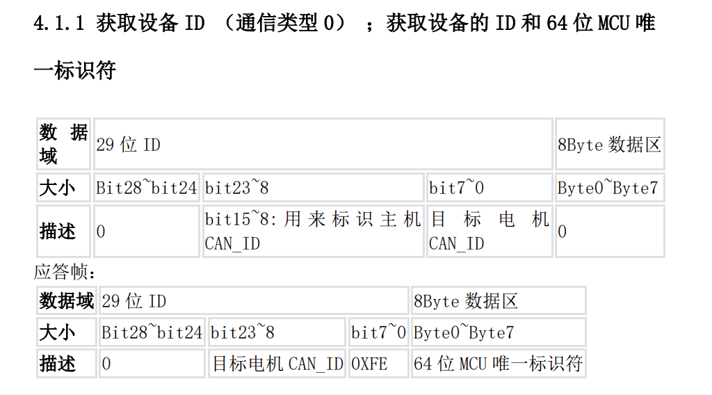
We just need to set the data frame as follows:
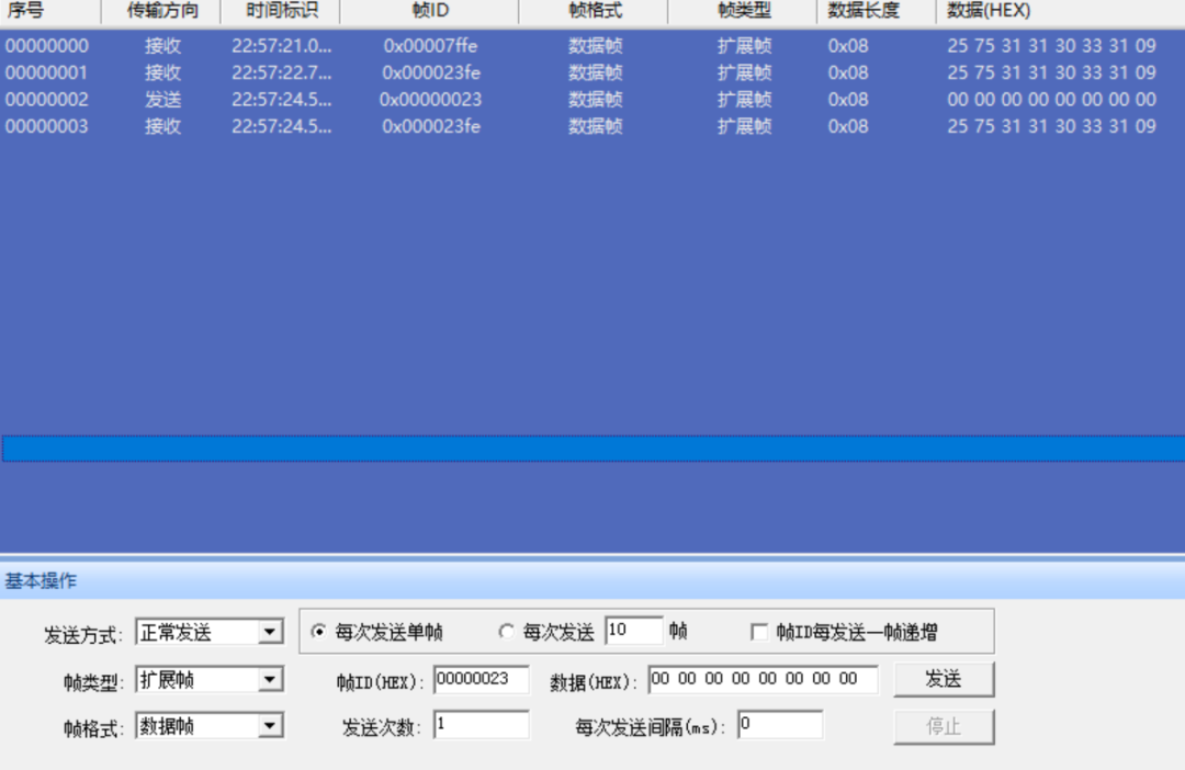
The first two in the figure are the data frames sent when the motor is powered on, and the third is the data frame we sent.
Here, we set the ID to: 0x00000023, and the data to: 0x00 00 00 00 00 00 00 00.
We can see that the motor response frame is the fourth data frame in the figure.
As for other communication types, they are quite similar; you can read the communication protocol in the manual.
3. Xiaomi Motor Driver Library
Special thanks to the expert ZDYukino. I made some modifications to this library so that it can send on two CANs on the 105.
However, this library does not have detailed explanations, and as a beginner, I still encountered many pitfalls. The code will be provided at the end of this article.
Here, we will give a summary analysis of this driver library and will drive the motor in the next chapter with examples.
Main Logic & Functions:
1. Defined some global variables and macros, including data structures and variables related to CAN communication.
2. Implemented some auxiliary functions:
Float_to_Byte converts a floating-point number to a byte array.
uint16_to_float converts a 16-bit unsigned integer to a floating-point number.
float_to_uint converts a floating-point number to an unsigned integer of a specified bit length.
Set_Motor_Parameter sets the motor parameters, converting the parameter value to a byte array according to the parameter type and sending it to the motor via CAN.
Get_Motor_ID extracts the motor ID from the received CAN ID.
3. Implemented some functions to control the motor:
chack_cybergear checks the motor’s status.
start_cybergear starts the motor.
stop_cybergear stops the motor.
set_mode_cybergear sets the motor’s working mode.
set_current_cybergear sets the motor’s current.
set_zeropos_cybergear sets the motor’s zero position.
set_CANID_cybergear sets the motor’s CAN ID.
init_cybergear initializes the motor, setting its ID and mode, and starts the motor.
motor_controlmode controls the motor’s motion mode, including torque, mechanical position, speed, control parameters, etc.
4. Implemented a CAN reception callback function HAL_CAN_RxFifo1MsgPendingCallback, which is triggered when a CAN message arrives. In this function, the received data is extracted and saved into the corresponding motor structure based on the received motor ID.
For the header file:
1. Defined some macros, including minimum and maximum values for control parameters, as well as macro definitions for communication commands.
2. Defined an enumeration type CONTROL_MODE to represent the motor’s control modes, including operation mode, position mode, speed mode, and current mode.
3. Defined an enumeration type ERROR_TAG to represent the motor’s error states.
4. Defined a structure MI_Motor to represent the Xiaomi motor. This structure contains some state information of the motor, such as CAN ID, MCU ID, angle, speed, torque, temperature, etc. It also contains some variables for setting motor parameters, such as set current, set speed, and set position.
5. Declared some function prototypes, including checking motor status, starting the motor, stopping the motor, setting the motor’s working mode, setting the motor’s current, setting the motor’s zero position, setting the motor’s CAN ID, initializing the motor, and controlling the motor’s motion mode.
/** ****************************(C)SWJTU_ROBOTCON**************************** * @file cybergear.c/h * @brief Xiaomi Motor Function Library * @note * @history * Version Date Author Modification * V1.0.0 1-10-2023 ZDYukino 1. done * @verbatim ========================================================================= ========================================================================= @endverbatim ****************************(C)SWJTU_ROBOTCON**************************** **/#include "main.h"#include "can.h"#include "cybergear.h"//#include "vofa.h"
CAN_RxHeaderTypeDef rxMsg;//Receive structure
CAN_TxHeaderTypeDef txMsg;//Send configuration structure
uint8_t rx_data[8];       //Receive data
uint32_t Motor_Can_ID;    //Receive data motor ID
uint8_t byte[4];          //Temporary data conversion
uint32_t send_mail_box = {0};//NONE
#define can_txd() HAL_CAN_AddTxMessage(&hcan1, &txMsg, tx_data, &send_mail_box)//CAN sending macro
MI_Motor mi_motor[4];//Predefine four Xiaomi motors
/** * @brief Convert floating point to 4 bytes function * @param[in] f: floating point number * @retval 4 byte array * @description : IEEE 754 protocol */static uint8_t* Float_to_Byte(float f){    unsigned long longdata = 0;    longdata = *(unsigned long*)&f           byte[0] = (longdata & 0xFF000000) >> 24;    byte[1] = (longdata & 0x00FF0000) >> 16;                                                                                                                                                                                                             byte[2] = (longdata & 0x0000FF00) >> 8;    byte[3] = (longdata & 0x000000FF);    return byte;}
/** * @brief Convert Xiaomi motor 16-bit data to floating point * @param[in] x: 16-bit data * @param[in] x_min: corresponding parameter lower limit * @param[in] x_max: corresponding parameter upper limit * @param[in] bits: parameter bit count * @retval Returns floating point value */static float uint16_to_float(uint16_t x,float x_min,float x_max,int bits){    uint32_t span = (1 << bits) - 1;    float offset = x_max - x_min;    return offset * x / span + x_min;}
/** * @brief Send floating point as 16-bit data to Xiaomi motor * @param[in] x: floating point * @param[in] x_min: corresponding parameter lower limit * @param[in] x_max: corresponding parameter upper limit * @param[in] bits: parameter bit count * @retval Returns floating point value */static int float_to_uint(float x, float x_min, float x_max, int bits){  float span = x_max - x_min;  float offset = x_min;  if(x > x_max) x=x_max;  else if(x < x_min) x= x_min;  return (int) ((x-offset)*((float)((1<<bits)-1))/span);}
/** * @brief Write motor parameters * @param[in] Motor: corresponding control motor structure * @param[in] Index: address for writing parameters * @param[in] Value: value of the parameter to write * @param[in] Value_type: data type of the parameter to write * @retval none */static void Set_Motor_Parameter(MI_Motor *Motor,uint16_t Index,float Value,char Value_type){    uint8_t tx_data[8];    txMsg.ExtId = Communication_Type_SetSingleParameter<<24|Master_CAN_ID<<8|Motor->CAN_ID;    tx_data[0]=Index;    tx_data[1]=Index>>8;    tx_data[2]=0x00;    tx_data[3]=0x00;    if(Value_type == 'f'){        Float_to_Byte(Value);        tx_data[4]=byte[3];        tx_data[5]=byte[2];        tx_data[6]=byte[1];        tx_data[7]=byte[0];            }    else if(Value_type == 's'){        tx_data[4]=(uint8_t)Value;        tx_data[5]=0x00;        tx_data[6]=0x00;        tx_data[7]=0x00;                    }    can_txd();    }
/** * @brief Extract motor reply frame extended ID from motor CANID * @param[in] CAN_ID_Frame: extended CANID in motor reply frame * @retval motor CANID */static uint32_t Get_Motor_ID(uint32_t CAN_ID_Frame){    return (CAN_ID_Frame&0xFFFF)>>8;}
/** * @brief Motor reply frame data processing function * @param[in] Motor: corresponding control motor structure * @param[in] DataFrame: data frame * @param[in] IDFrame: extended ID frame * @retval None */static void Motor_Data_Handler(MI_Motor *Motor,uint8_t DataFrame[8],uint32_t IDFrame){            Motor->Angle=uint16_to_float(DataFrame[0]<<8|DataFrame[1],MIN_P,MAX_P,16);        Motor->Speed=uint16_to_float(DataFrame[2]<<8|DataFrame[3],V_MIN,V_MAX,16);                    Motor->Torque=uint16_to_float(DataFrame[4]<<8|DataFrame[5],T_MIN,T_MAX,16);                        Motor->Temp=(DataFrame[6]<<8|DataFrame[7])*Temp_Gain;        Motor->error_code=(IDFrame&0x1F0000)>>16;    }
/** * @brief Check Xiaomi motor ID * @param[in] id: corresponding control motor structure * @retval none */void chack_cybergear(uint8_t ID){    uint8_t tx_data[8] = {0};    txMsg.ExtId = Communication_Type_GetID<<24|Master_CAN_ID<<8|ID;    can_txd();}
/** * @brief Enable Xiaomi motor * @param[in] Motor: corresponding control motor structure * @retval none */void start_cybergear(MI_Motor *Motor){    uint8_t tx_data[8] = {0};     txMsg.ExtId = Communication_Type_MotorEnable<<24|Master_CAN_ID<<8|Motor->CAN_ID;    can_txd();}
/** * @brief Stop motor * @param[in] Motor: corresponding control motor structure * @param[in] clear_error: clear error bit (0 do not clear 1 clear) * @retval None */void stop_cybergear(MI_Motor *Motor,uint8_t clear_error){    uint8_t tx_data[8]={0};    tx_data[0]=clear_error;//clear error bit setting    txMsg.ExtId = Communication_Type_MotorStop<<24|Master_CAN_ID<<8|Motor->CAN_ID;    can_txd();}
/** * @brief Set motor mode (must stop to adjust!) * @param[in] Motor: motor structure * @param[in] Mode: motor working mode (1. motion mode Motion_mode 2. position mode Position_mode 3. speed mode Speed_mode 4. current mode Current_mode) * @retval none */void set_mode_cybergear(MI_Motor *Motor,uint8_t Mode){        Set_Motor_Parameter(Motor,Run_mode,Mode,'s');}
/** * @brief Set current in current control mode * @param[in] Motor: motor structure * @param[in] Current: current setting * @retval none */void set_current_cybergear(MI_Motor *Motor,float Current){    Set_Motor_Parameter(Motor,Iq_Ref,Current,'f');}
/** * @brief Set motor zero position * @param[in] Motor: motor structure * @retval none */void set_zeropos_cybergear(MI_Motor *Motor){    uint8_t tx_data[8]={0};    txMsg.ExtId = Communication_Type_SetPosZero<<24|Master_CAN_ID<<8|Motor->CAN_ID;    can_txd();        }
/** * @brief Set motor CANID * @param[in] Motor: motor structure * @param[in] Motor: set new ID * @retval none */void set_CANID_cybergear(MI_Motor *Motor,uint8_t CAN_ID){    uint8_t tx_data[8];    txMsg.ExtId = Communication_Type_CanID<<24|CAN_ID<<16|Master_CAN_ID<<8|Motor->CAN_ID;    Motor->CAN_ID = CAN_ID;//Import new ID into motor structure    can_txd();    }
/** * @brief Initialize Xiaomi motor * @param[in] Motor: motor structure * @param[in] Can_Id: Xiaomi motor ID (default 0x7F) * @param[in] Motor_Num: motor number * @param[in] mode: motor working mode (0. motion mode Motion_mode 1. position mode Position_mode 2. speed mode Speed_mode 3. current mode Current_mode) * @retval none */void init_cybergear(MI_Motor *Motor,uint8_t Can_Id, uint8_t mode){    txMsg.StdId = 0;            //Configure CAN sending: standard frame clear     txMsg.ExtId = 0;            //Configure CAN sending: extended frame clear     txMsg.IDE = CAN_ID_EXT;     //Configure CAN sending: extended frame    txMsg.RTR = CAN_RTR_DATA;   //Configure CAN sending: data frame    txMsg.DLC = 0x08;           //Configure CAN sending: data length
    Motor->CAN_ID=Can_Id;       //ID setting     set_mode_cybergear(Motor,mode);//Set motor mode    start_cybergear(Motor);        //Enable motor}
/** * @brief Xiaomi motion control mode command * @param[in] Motor: target motor structure * @param[in] torque: torque setting [-12,12] N*M * @param[in] MechPosition: position setting [-12.5,12.5] rad * @param[in] speed: speed setting [-30,30] rpm * @param[in] kp: proportional parameter setting * @param[in] kd: differential parameter setting * @retval none */void motor_controlmode(MI_Motor *Motor,float torque, float MechPosition, float speed, float kp, float kd){       uint8_t tx_data[8];//Initialize sending data    //Load sending data    tx_data[0]=float_to_uint(MechPosition,P_MIN,P_MAX,16)>>8;      tx_data[1]=float_to_uint(MechPosition,P_MIN,P_MAX,16);      tx_data[2]=float_to_uint(speed,V_MIN,V_MAX,16)>>8;      tx_data[3]=float_to_uint(speed,V_MIN,V_MAX,16);      tx_data[4]=float_to_uint(kp,KP_MIN,KP_MAX,16)>>8;      tx_data[5]=float_to_uint(kp,KP_MIN,KP_MAX,16);      tx_data[6]=float_to_uint(kd,KD_MIN,KD_MAX,16)>>8;      tx_data[7]=float_to_uint(kd,KD_MIN,KD_MAX,16);
    txMsg.ExtId = Communication_Type_MotionControl<<24|float_to_uint(torque,T_MIN,T_MAX,16)<<8|Motor->CAN_ID;//Load extended frame data    can_txd();}
/*****************************Callback function responsible for receiving back information can be transferred elsewhere*****************************//** * @brief HAL library CAN callback function, receiving motor data * @param[in] hcan: CAN handle pointer * @retval none */void HAL_CAN_RxFifo1MsgPendingCallback(CAN_HandleTypeDef *hcan){    //HAL_GPIO_TogglePin(LED1_GPIO_Port,LED1_Pin); //LED flash indication    HAL_CAN_GetRxMessage(hcan, CAN_RX_FIFO1, &rxMsg, rx_data);//Receive data    Motor_Can_ID=Get_Motor_ID(rxMsg.ExtId);//First obtain the returned motor ID information     switch(Motor_Can_ID)                   //Extract corresponding motor information into corresponding structure    {        case 0X7F:              if(rxMsg.ExtId>>24 != 0)               //Check if it is in broadcast mode                Motor_Data_Handler(&mi_motor[0],rx_data,rxMsg.ExtId);            else                 mi_motor[0].MCU_ID = rx_data[0];            break;                   default:            break;            }}
/** ****************************(C)SWJTU_ROBOTCON**************************** * @file cybergear.c/h * @brief Xiaomi Motor Function Library * @note * @history * Version Date Author Modification * V1.0.0 1-10-2023 ZDYukino 1. done * @verbatim ========================================================================= ========================================================================= @endverbatim ****************************(C)SWJTU_ROBOTCON**************************** **/#include "main.h"#include "can.h"//Control parameter limits, change with caution
#define P_MIN -12.5f#define P_MAX 12.5f#define V_MIN -30.0f#define V_MAX 30.0f#define KP_MIN 0.0f#define KP_MAX 500.0f#define KD_MIN 0.0f#define KD_MAX 5.0f#define T_MIN -12.0f#define T_MAX 12.0f#define MAX_P 720#define MIN_P -720//Host CANID settings#define Master_CAN_ID 0x00 //Host ID//Control command macro definitions#define Communication_Type_GetID 0x00 //Get device ID and 64-bit MCU unique identifier#define Communication_Type_MotionControl 0x01 //Send control commands to the host#define Communication_Type_MotorRequest 0x02 //Feedback motor operation status to the host#define Communication_Type_MotorEnable 0x03 //Enable motor operation#define Communication_Type_MotorStop 0x04 //Stop motor operation#define Communication_Type_SetPosZero 0x06 //Set motor mechanical zero position#define Communication_Type_CanID 0x07 //Change current motor CAN_ID#define Communication_Type_Control_Mode 0x12#define Communication_Type_GetSingleParameter 0x11 //Read single parameter#define Communication_Type_SetSingleParameter 0x12 //Set single parameter#define Communication_Type_ErrorFeedback 0x15 //Fault feedback frame//Parameter reading macro definitions#define Run_mode 0x7005 #define Iq_Ref 0x7006#define Spd_Ref 0x700A#define Limit_Torque 0x700B#define Cur_Kp 0x7010#define Cur_Ki 0x7011#define Cur_Filt_Gain 0x7014#define Loc_Ref 0x7016#define Limit_Spd 0x7017#define Limit_Cur 0x7018
#define Gain_Angle 720/32767.0#define Bias_Angle 0x8000#define Gain_Speed 30/32767.0#define Bias_Speed 0x8000#define Gain_Torque 12/32767.0#define Bias_Torque 0x8000#define Temp_Gain 0.1
#define Motor_Error 0x00#define Motor_OK 0X01
enum CONTROL_MODE //Control mode definition{ Motion_mode = 0,//Operation mode Position_mode, //Position mode Speed_mode, //Position mode Current_mode //Current mode};enum ERROR_TAG //Error feedback correspondence{ OK = 0,//No fault BAT_LOW_ERR = 1,//Under-voltage fault OVER_CURRENT_ERR = 2,//Overcurrent OVER_TEMP_ERR = 3,//Overtemperature MAGNETIC_ERR = 4,//Magnetic encoder fault HALL_ERR_ERR = 5,//HALL encoder fault NO_CALIBRATION_ERR = 6//Not calibrated};typedef struct{ //Xiaomi motor structure uint8_t CAN_ID; //CAN ID uint8_t MCU_ID; //MCU unique identifier [last 8 bits, total 64 bits] float Angle; //Return angle float Speed; //Return speed float Torque; //Return torque float Temp;
uint16_t set_current; uint16_t set_speed; uint16_t set_position;
uint8_t error_code;
float Angle_Bias;
}MI_Motor;extern MI_Motor mi_motor[4];//Predefine four Xiaomi motors
extern void chack_cybergear(uint8_t ID);extern void start_cybergear(MI_Motor *Motor);extern void stop_cybergear(MI_Motor *Motor, uint8_t clear_error);extern void set_mode_cybergear(MI_Motor *Motor, uint8_t Mode);extern void set_current_cybergear(MI_Motor *Motor, float Current);extern void set_zeropos_cybergear(MI_Motor *Motor);extern void set_CANID_cybergear(MI_Motor *Motor, uint8_t CAN_ID);extern void init_cybergear(MI_Motor *Motor, uint8_t Can_Id, uint8_t mode);extern void motor_controlmode(MI_Motor *Motor,float torque, float MechPosition, float speed, float kp, float kd);


Click Read Original, to purchase the OriginCar intelligent robot kit.