Click on the “Technical Training” above, and select “Top Public Account“
160,000+ industrial control professionals follow this WeChat platform: technical sharing, learning exchanges, industrial control videos
Recently, some fans inquired about Siemens encoders, so today I will share content about the S7-1200 PLC. Let’s take a look!
1. Connecting Siemens S7-1200 to Incremental Encoders
The digital input switch points of the Siemens S7-1200 provide a fast counter function for incremental encoder pulse signals, with a single-phase signal reaching 200KHz and a dual-phase signal (which can quadruple frequency and determine direction) reaching 80KHz. For commonly used 2500PPR (pulses per revolution), the maximum speed can reach 1920RPM (revolutions per minute). The signal from the incremental encoder is a PNP unidirectional open circuit signal, and it is recommended to select incremental encoders with a push-pull output type in the range of 10-30V, such as the GI58N incremental encoder.
2. Connecting Siemens S7-1200 to Absolute Encoders with 4-20mA Signals
Absolute encoder signals are immune to interference, and data is not lost during power outages. The PLC does not need to constantly count for absolute encoders, thus saving CPU resources, especially as the market price of absolute encoders has significantly decreased. With improved data reliability, using absolute encoders can save debugging time and reduce after-sales service costs. The actual performance and cost-effectiveness have far surpassed that of incremental encoders, and more users are leaning towards using absolute encoders for PLC position positioning.
Due to the cost-effectiveness of the S7-1200, the preferred connection to absolute encoders is the economical and convenient 4-20mA signal interface. The Siemens S7-1200 has two built-in 4-20mA input interfaces, allowing direct connection to two absolute encoders with 4-20mA output interfaces.
Absolute encoders are divided into single-turn and multi-turn types. A single-turn absolute encoder works within a rotation of 360 degrees or 0-180 degrees. In this case, 4mA corresponds to 0 degrees, and 360 degrees (or 180 degrees) corresponds to 20mA. The data in the PLC linearly corresponds to angle values, with each value corresponding to a unique angle, without the need for counting and immune to interference and power outages, allowing for direct programming. It is recommended to use the GMS412.LB (code 9400S) single-turn absolute encoder, which can set the angle value and rotation direction corresponding to 20mA, as well as zero offset. For example, 20mA can correspond to 180 degrees, with the encoder working within 0-180 degrees.
In applications requiring length or height PLC positioning control, where the encoder needs to rotate beyond 360 degrees, a multi-turn absolute encoder should be selected. The 4-20mA output of multi-turn absolute encoders comes in two types: fixed range multi-turn absolute encoders, such as 16 turns, 64 turns, and 256 turns, with 20mA corresponding to the endpoint of 16 turns, 64 turns, or 256 turns. These encoders are more economical, and the recommended model is GEX60.LB. The other type is intelligent multi-turn absolute encoders, where 20mA can be set to any position between 1-4096 turns, with zero offset settings. The recommended model is GAX60.LB (code 9600), which is widely used in various fields such as lifting, water conservancy, military, petroleum, chemical, and industrial machinery.
3. Connecting Siemens S7-1200 to Absolute Encoders with RS485 or Modbus RTU Signals
The Siemens S7-1200 can be configured with an RS485 communication interface, which can connect to the RS485 signals of absolute encoders, including single-turn and multi-turn types. The RS485 signal of absolute encoders has various forms, commonly including simple RS485 broadcast mode (master mode actively broadcasts), addressable free protocol (slave passive mode), and Modbus RTU mode. If only one absolute encoder is connected, the encoder active mode can be used, which is simple and reliable. However, if multiple encoders are to be connected (bus mode), Modbus RTU mode is preferred. This method, however, requires polling, resulting in slower data refresh rates for each encoder, making it unsuitable for fast-moving control.
The recommended active mode RS485 encoders for single-turn absolute are GES38.RDB, GES60.RDB, or GMS412.LB (code 9400S); for multi-turn absolute, the models are GEX60.LB (64 turns) or GAX60.LB (code 9600, 4096 turns).
The recommended passive command mode RS485 encoders (which can connect 1-9 encoders with addresses) for single-turn absolute are GMS412.LB (code 9400S); for multi-turn absolute, the models are GEX60.LB (64 turns) or GAX60.LB (code 9600, 4096 turns).
The recommended Modbus RTU mode encoders for single-turn absolute are GMS412.RMB; for multi-turn absolute, the model is GAX60.RMB (4096 turns).
4. Connecting Siemens S7-1200 to Absolute Encoders with Profibus-DP Signals
The Siemens S7-1200 can be configured with a Profibus-DP bus communication interface, which is the most commonly used output mode for European absolute encoders. It can select various European imported brand encoders, including domestic brand absolute encoders. This interface is commonly used by Siemens; however, the cost of encoders with this interface is high, including the cost of cable wiring, making it unsuitable for the cost-effectiveness of the S7-1200, and is not recommended here.
5. Practical Case: Connecting Siemens S7-1200 to Absolute Encoders with 4-20mA Signals for Simple Position Control
Practical Application 1: Control of the height of sluice gates in hydraulic systems, where the lifting and closing of flood control, storage, water supply, and sewage sluices across the country are performed by hoisting machines. Each sluice station has 1-6 gate hoisting machines, and the Siemens S7-1200 PLC connects to the 4-20mA interface of the absolute multi-turn encoder, configured with HMI, to effectively complete such simple position control.
The encoder can be installed on the drum shaft of the winch or the reduction gear shaft. The required number of rotations for the encoder is pre-calculated, and the encoder output of 20mA is set to be greater than this number, for example, 16 turns. Thus, every change of 1mA in the 4-20mA output corresponds linearly to one rotation of the drum, calculating the height change of the sluice gate to control the opening and closing height of the sluice gate. The selected encoder model is the GAX60.LB (code 9600) mentioned above, with project applications in multiple sluices in Northeast Harbin, Jiangsu Changzhou, and other locations.
Practical Application 2: Synchronous control of hydraulic double cylinders, where larger sluice gates require the use of two hydraulic cylinders on the left and right for lifting, maintaining synchronous positions to ensure smooth lifting and lowering of the gate. A certain sluice in Guangdong originally used a gate opening instrument only for display. Due to the low reliability of the original display instrument, it could not complete the synchronous correction and lifting control of the hydraulic cylinders. The user hoped to replace the original display instrument with a small, economical PLC and HMI to improve control reliability and programmability. The Siemens S7-1200 was chosen for the PLC, and the absolute multi-turn encoder with a 4-20mA signal interface, GAX60.LB (code 9600), was used in two units, mechanically installed corresponding to the lifting heights of the left and right cylinders. The corresponding height of 6 meters for the cylinders corresponds to 20mA, and the two 4-20mA signals connect to the analog interfaces of the S7-1200. The PLC compares the two sets of data and controls the electromagnetic valves of the hydraulic system of the left and right cylinders based on the height differences, adjusting the flow rate of the hydraulic oil to control the lifting or lowering speed and position difference of the cylinders, maintaining synchronous correction of the lifting control. The Siemens S7-1200 effectively completed such synchronous correction and lifting control with two absolute encoders with 4-20mA interfaces.
6. How to Use Siemens PLC to Connect Encoders and Program the Encoders
The required hardware includes:
1. PLC: Siemens S7-1200-CPU1214C/DC/DC/DC, V4.1.
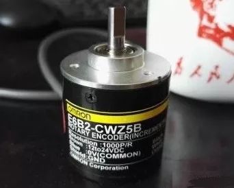
2. Encoder: E6B2-CWZ5B, PNP, incremental type, 1000P/R, as shown below:
3. Wiring of the encoder to the PLC, as shown below:
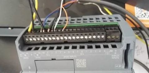
Brown: DC24V+
Blue: COM
Black: A, connect to I0.0
White: B, connect to I0.1
Orange: Z, connect to I0.3
Points A and B can be defined by the user and do not necessarily have to be I0.0 and I0.1, while Z cannot be changed.
4. Configure the high-speed counter, as shown below:
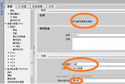
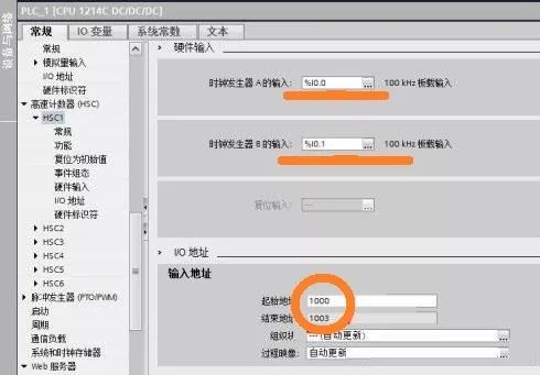
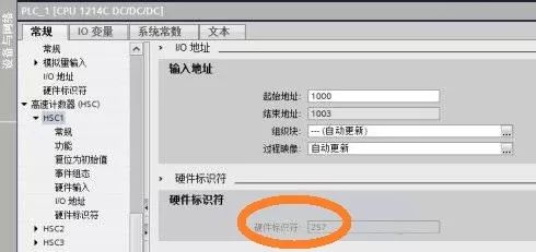
Here, select HSC1, enable the high-speed counter, counting, A/B counting, and increment counting. Use the default address ID1000 as the counter address, but other addresses can also be chosen, occupying four bytes.
5. Pay attention to the filter issues of the IO channels being used, as shown below:
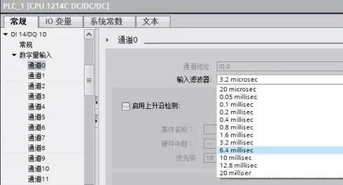
In older CPU versions, the filtering is disabled when using high-speed counters, so this is not a concern. However, in version V4.1 of the CPU, it is not disabled, so attention must be paid to the filtering and the pulse frequency of the encoder. If they are not suitable, they will be filtered out.
6. Monitor the test results, as shown below:
You can read the results without writing a program. Only when special functions are needed will programming be required, which is not covered here.
7. Filter time and the maximum frequency that can be detected, as shown below:
What type of encoders do you usually encounter? Source: Internet, please delete if infringing
Share with friends and learn together!
Click to read the original text to learn about electrical engineering, PLC, frequency conversion servo, CNC robots, and more.