1. Making the Obstacle Avoidance Car
1. Preparations for Making the Obstacle Avoidance Car
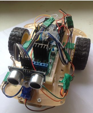
Hardware: Arduino UNO, L298N driver module, ultrasonic module, car chassis, servo module, a breadboard, and some Dupont wires.
Software: Arduino UNO programming download software
Here is an image of the installed setup:
2. Understanding the Servo Module
We are using a simple and practical 9g servo.
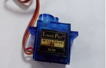
Its torque is not very high, but it is sufficient for our purpose of scanning with an ultrasonic distance sensor. Generally, servos have a rotation angle range of 0-180 degrees. There are also digital motors that can switch between motor and servo states, allowing for precise angle control and continuous rotation as a motor. The angle of rotation of the servo is determined by the pulse width from the controller. If the servo is in the middle position (90 degrees), the pulse width is set to 1.5ms. To turn the servo to 0 degrees, a 1ms pulse is sent; to turn it to 180 degrees, a 2ms pulse is sent. This is the basic principle of servo angle control.
3. Understanding the Ultrasonic Module
The ultrasonic module used is shown below:
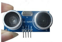
Module working principle:
1. Use IO to trigger distance measurement, sending a high-level signal of at least 10us;
2. The module automatically sends 8 pulses of 40KHz and detects if there is a signal returned;
3. If a signal is returned, it outputs a high level through IO, and the duration of the high level is the time taken for the ultrasonic wave to travel out and back. Testing distance = (High level time * speed of sound (340m/s)) / 2;
4. Understanding the L298N Module
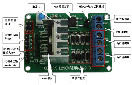
The L298N module used is shown below:
1. Driver chip: L298N dual H-bridge DC motor driver chip
2. Power supply range for the driver section terminals Vs: +5V to +35V; if power is taken from the board, the supply range Vs: +7V to +35V
3. Peak current Io for the driver section: 2A
4. Working current range for the logic section: 0 to 36mA
6. Control signal input voltage range (IN1 IN2 IN3 IN4):
Low level: -0.3V ≤ Vin ≤ 1.5V
High level: 2.3V ≤ Vin ≤ Vss
7. Enable signal input voltage range (ENA ENB):
Low level: -0.3 ≤ Vin ≤ 1.5V (control signal invalid)
High level: 2.3V ≤ Vin ≤ Vss (control signal valid)
8. Maximum power consumption: 20W (at temperature T = 75℃)
9. Storage temperature: -25℃ to +130℃
10. Driver board dimensions: 58mm * 40mm
12. Other extensions: Control direction indicator, internal power supply interface for the logic section.
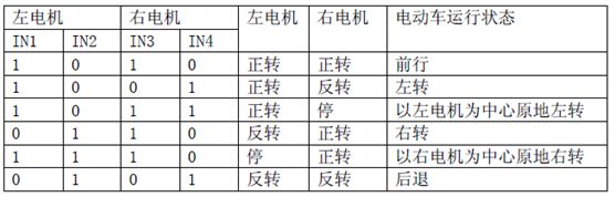
The L298N accepts standard TTL logic level signals VSS, VSS can connect to 4.5 to 7 V voltage. The 4th pin VS connects to the power supply voltage, and the VS voltage range VIH is +2.5 to 46 V. The output current can reach 2.5 A, capable of driving inductive loads. The L298 can drive 2 DC motors, OUT1, OUT2, and OUT3, OUT4 can be connected to DC motors respectively.
Motor rotation status encoding:
4. Understanding the Breadboard
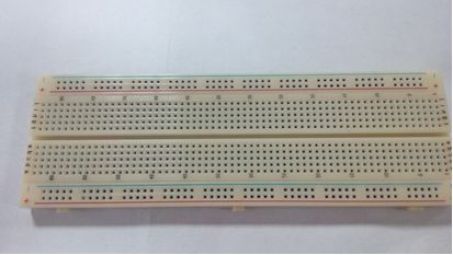
When using it, typically two narrow strips and one wide strip are used together. The first row of the two narrow strips is usually connected to the ground, and the second row is connected to the power supply. Since the power supply for integrated circuits is generally at the top and ground at the bottom, this layout helps connect the power pins of the integrated circuit to the upper second row narrow strip and the ground pins to the lower narrow strip’s first row, reducing the length of connections and the number of jumpers. The middle wide strip is used to connect circuits, and since the grooves are not connected vertically, the integrated circuit is generally inserted across the grooves. The middle wide strip has 5 pins, connected in series. Pins or wire cores inserted into the breadboard holes should have a diameter of 0.4 to 0.6mm, which is slightly thinner than the diameter of a pin. The component pins or wire ends should be inserted vertically into the holes of the breadboard, and there should be a slight, even friction resistance felt. When the breadboard is inverted, the components should be held by the spring clips and not fall out. The breadboard should be stored in a ventilated, dry place, especially avoiding corrosion from electrolyte leakage from batteries. The breadboard should be kept clean, and soldered components should not be inserted into the breadboard.
6. Analysis of the Overall Connection Diagram
(1) Arduino Connection to the Breadboard
Due to the limited number of pins on the Arduino UNO, power and GND need to be brought out, requiring the use of a breadboard. Connect the 5V from Arduino to the positive terminal of the breadboard, and the GND from Arduino to the negative terminal of the breadboard.
(2) Arduino Connection to the L298N Motor Driver Module
I1 I2 I3 I4: Motor control input terminals, directly connected to the microcontroller’s IO ports
OUT1 OUT2 OUT3 OUT4: Motor connection terminals.
SGND: Connect to the board’s GND
VIN: Motor power input terminal, voltage range +5V~+35v.
+5V: +5V power input/output terminal. When powering the L298N chip from an external source, this can be the chip’s power input terminal. When taking power from the board, it can also serve as a +5V power output pin. Connect Out1 and Out2 to the two pins of the DC motor, Out3 and Out4 to the two pins of another DC motor, VIN connects to the positive terminal of the breadboard, SGND connects to the negative terminal of the breadboard, and the L289N driver board’s I1, I2 connects to pins 6, 9 on the Arduino. The L289N driver board’s I3, I4 connects to pins 10, 11 on the Arduino, and the L289N driver board’s 5V connects to the positive terminal of the breadboard, while the L289N driver board’s GND connects to the negative terminal of the breadboard.
(3) Arduino Connection to the Ultrasonic Module
Connect the VCC on the ultrasonic module to the positive terminal of the breadboard, GND to the negative terminal of the breadboard, Echo to analog pin A0 on the Arduino, and Trig to analog pin A1 on the Arduino.
(4) Arduino Connection to the Servo Module
Connect the red wire of the servo to the positive terminal of the breadboard, the brown wire to the negative terminal, and the orange wire on the breadboard to digital pin 5 on the Arduino.
Program code:
#include <Servo.h>
int pinLB=6;
int pinLF=9;
int pinRB=10;
int pinRF=11;
int inputPin = A0;
int outputPin =A1;
int Fspeedd = 0;
int Rspeedd = 0;
int Lspeedd = 0;
int directionn = 0;
Servo myservo;
int delay_time = 250;
int Fgo = 8;
int Rgo = 6;
int Lgo = 4;
int Bgo = 2;
void setup()
{
Serial.begin(9600);
pinMode(pinLB,OUTPUT);
pinMode(pinLF,OUTPUT);
pinMode(pinRB,OUTPUT);
pinMode(pinRF,OUTPUT);
pinMode(inputPin, INPUT);
pinMode(outputPin, OUTPUT);
myservo.attach(5);
}
void advance(int a)
{
digitalWrite(pinRB,LOW);
digitalWrite(pinRF,HIGH);
digitalWrite(pinLB,LOW);
digitalWrite(pinLF,HIGH);
delay(a * 100);
}
void right(int b)
{
digitalWrite(pinRB,LOW);
digitalWrite(pinRF,HIGH);
digitalWrite(pinLB,HIGH);
digitalWrite(pinLF,HIGH);
delay(b * 100);
}
void left(int c)
{
digitalWrite(pinRB,HIGH);
digitalWrite(pinRF,HIGH);
digitalWrite(pinLB,LOW);
digitalWrite(pinLF,HIGH);
delay(c * 100);
}
void turnR(int d)
{
digitalWrite(pinRB,LOW);
digitalWrite(pinRF,HIGH);
digitalWrite(pinLB,HIGH);
digitalWrite(pinLF,LOW);
delay(d * 100);
}
void turnL(int e)
{
digitalWrite(pinRB,HIGH);
digitalWrite(pinRF,LOW);
digitalWrite(pinLB,LOW);
digitalWrite(pinLF,HIGH);
delay(e * 100);
}
void stopp(int f)
{
digitalWrite(pinRB,HIGH);
digitalWrite(pinRF,HIGH);
digitalWrite(pinLB,HIGH);
digitalWrite(pinLF,HIGH);
delay(f * 100);
}
void back(int g)
{
digitalWrite(pinRB,HIGH);
digitalWrite(pinRF,LOW);
digitalWrite(pinLB,HIGH);
digitalWrite(pinLF,LOW);
delay(g * 100);
}
void detection()
{
int delay_time = 250;
ask_pin_F();
if(Fspeedd < 10)
{
stopp(1);
back(2);
}
if(Fspeedd < 25)
{
stopp(1);
ask_pin_L();
delay(delay_time);
ask_pin_R();
delay(delay_time);
if(Lspeedd > Rspeedd)
{
directionn = Rgo;
}
if(Lspeedd <= Rspeedd)
{
directionn = Lgo;
}
if (Lspeedd < 10 && Rspeedd < 10)
{
directionn = Bgo;
}
}
else
{
directionn = Fgo;
}
}
void ask_pin_F()
{
myservo.write(90);
digitalWrite(outputPin, LOW);
delayMicroseconds(2);
digitalWrite(outputPin, HIGH);
delayMicroseconds(10);
digitalWrite(outputPin, LOW);
float Fdistance = pulseIn(inputPin, HIGH);
Fdistance= Fdistance/5.8/10;
Serial.print(“F distance:”);
Serial.println(Fdistance);
Fspeedd = Fdistance;
}
void ask_pin_L()
{
myservo.write(5);
delay(delay_time);
digitalWrite(outputPin, LOW);
delayMicroseconds(2);
digitalWrite(outputPin, HIGH);
delayMicroseconds(10);
digitalWrite(outputPin, LOW);
float Ldistance = pulseIn(inputPin, HIGH);
Ldistance= Ldistance/5.8/10;
Serial.print(“L distance:”);
Serial.println(Ldistance);
Lspeedd = Ldistance;
}
void ask_pin_R()
{
myservo.write(177);
delay(delay_time);
digitalWrite(outputPin, LOW);
delayMicroseconds(2);
digitalWrite(outputPin, HIGH);
delayMicroseconds(10);
digitalWrite(outputPin, LOW);
float Rdistance = pulseIn(inputPin, HIGH);
Rdistance= Rdistance/5.8/10;
Serial.print(“R distance:”);
Serial.println(Rdistance);
Rspeedd = Rdistance;
}
void loop()
{
myservo.write(90);
detection();
if(directionn == 2)
{
back(8);
turnL(2);
Serial.print(” Reverse “);
}
if(directionn == 6)
{
back(1);
turnR(6);
Serial.print(” Right “);
}
if(directionn == 4)
{
back(1);
turnL(6);
Serial.print(” Left “);
}
if(directionn == 8)
{
advance(1);
Serial.print(” Advance “);
Serial.print(” “);
}
}
The hardware purchase links are as follows:
cepark.taobao.com