What is the working principle of lcd1602?
1. Segment Display
The dot matrix liquid crystal consists of M×N display units. Assuming the LCD screen has 64 rows and each row has 128 columns, every 8 columns correspond to 1 byte of 8 bits, meaning each row consists of 16 bytes, totaling 16×8=128 dots. The screen has 64×16 display units corresponding to a display RAM area of 1024 bytes. The content of each byte corresponds to the brightness of the respective position on the display. For example, the brightness of the first row of the screen is determined by the content of 16 bytes from the RAM area 000H to 00FH. When (000H)=FFH, a short bright line of 8 dots appears in the upper left corner of the screen; when (3FFH)=FFH, a short bright line appears in the lower right corner. When (000H)=FFH, (001H)=00H, (002H)=00H, …, (00EH)=00H, (00FH)=00H, a dashed line composed of 8 bright segments and 8 dark segments appears at the top of the screen. This is the basic principle of LCD display.
2. Character Display
Displaying a character on the LCD is relatively complex because a character consists of a 6×8 or 8×8 dot matrix. It is necessary to find the corresponding 8 bytes in the display RAM for certain positions on the screen and ensure that the different bits of each byte are set to “1” for illumination and “0” for non-illumination. This forms a specific character. However, with a built-in character generator, displaying characters becomes simpler. The controller can operate in text mode, find the corresponding address in the display RAM based on the starting row and column number on the LCD, set the cursor, and send the code for the character to be displayed.
3. Displaying Chinese Characters
Chinese characters are generally displayed in graphical form. The dot matrix code for the characters to be displayed is extracted from a microcomputer in advance (usually using font extraction software). Each Chinese character occupies 32B, split into two halves, each occupying 16B. The left side corresponds to odd bytes (1, 3, 5,…) and the right side corresponds to even bytes (2, 4, 6,…). Based on the starting row and column number on the LCD, the corresponding address in the display RAM can be found, the cursor can be set, and the first byte of the Chinese character can be sent. The cursor position is incremented by 1, the second byte is sent, and so on until all 32B are displayed, resulting in a complete Chinese character on the LCD.
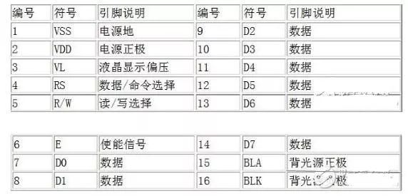
Pin Diagram and Function Description of lcd1602
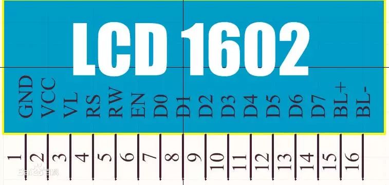
The 1602 LCD uses a standard 14-pin (without backlight) or 16-pin (with backlight) interface. The description of each pin is shown in Table 10-13:
Pin 1: GND is the ground power supply
Pin 2: VCC connects to the positive terminal of a 5V power supply
Pin 3: V0 is the contrast adjustment terminal for the LCD. When connected to the positive power supply, the contrast is weakest; when grounded, the contrast is highest (too high contrast may cause ghosting, which can be adjusted using a 10K potentiometer).
Pin 4: RS is the register select. High level (1) selects the data register; low level (0) selects the instruction register.
Pin 5: RW is the read/write signal line. High level (1) performs read operations, while low level (0) performs write operations.
Pin 6: E (or EN) is the enable pin. High level (1) reads information; negative edge triggers the execution of instructions.
Pins 7-14: D0-D7 are 8-bit bidirectional data pins. Pins 15-16: Unused pins or backlight power supply. Pin 15 is the positive terminal of the backlight, and pin 16 is the negative terminal.
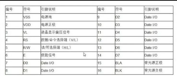
Method to Connect Arduino to LCD1602
Wiring diagram for Arduino and LCD
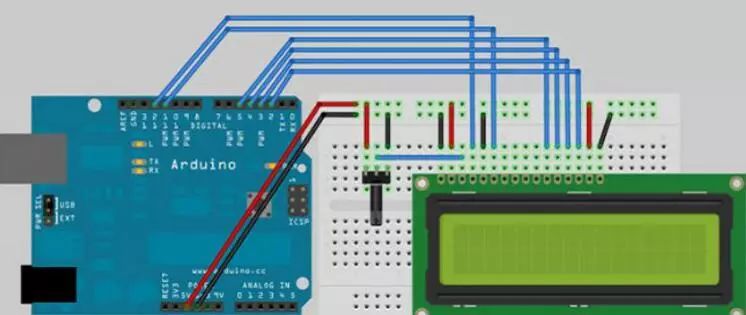
Pin connection description: The above diagram starts counting from the first pin from left to right:
1 Vss Ground (0V)
2 Vdd Power Supply (+5V)
3 Vo or Vee – Contrast adjustment (0-5V), can connect a 1K resistor or a 5K potentiometer
4 RS Register Select: Parameters: {1: D0 – D7 set to 1 for data interpretation; 0: D0 – D7 set to 0 for instruction interpretation}
5 R/W Read/Write mode: Parameters: {1: read data from LCD; 0: write data to LCD (generally, reading from the LCD is rare, connecting this pin to ground can save I/O pins)}
6 E Enable
7 D0 Bit 0 LSB
8 D1 Bit 1
9 D2 Bit 2
10 D3 Bit 3
11 D4 Bit 4
12 D5 Bit 5
13 D6 Bit 6
14 D7 Bit 7 MSB
15 A+ Backlight (connect a 1K resistor to ground or connect a 5K potentiometer to adjust backlight)
16 K- Backlight (GND)
This diagram was obtained from the Geek Workshop website:
Below is the code:
#include
LiquidCrystal lcd(12, 11, 5, 4, 3, 2); // Define pin numbers
void setup()
{
lcd.begin(16, 2); // Set the number of LCD displays. 16 X 2: 16 columns 2 rows.
lcd.print(“hello, world!”); // Display hello, world! on the LCD
}
void loop()
{
lcd.setCursor(0, 1); // Set the blinking cursor to column 0, line 1 (Note: counting starts from 0, line 0 is the first line, line 1 is the second line.)
lcd.print(millis()/1000); // Display the time in seconds since powering on
}
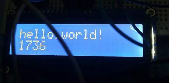
After uploading the code to Arduino, it displays as shown in the following image


To help everyone learn better, Changxue Electronics has specially added a public account for microcontroller and EDA knowledge, pushing related knowledge daily, hoping to assist in your learning!