Click ↑↑ on the above blue text “Computer Learning Room” to follow the public account, set the top right “…” as ★ starred★ to receive updates first every day~
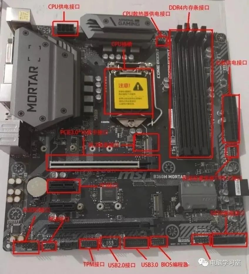
Today, I will give you a detailed explanation of the various interface types and functions on the computer motherboard and how to connect them.
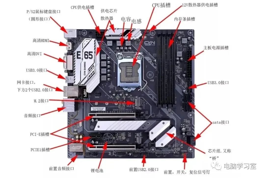
1. Motherboard Power Interface:

Motherboard power interface
There are two sizes for the motherboard power interface: 24 Pin or 20 Pin.
The 20 Pin interface is found only in very old computers; most power supplies now have a 24 Pin connector. It can be divided into 4 Pin and 20 Pin plugs.

Now almost every interface on the motherboard has a foolproof design, which makes it impossible for you to connect incorrectly unless you apply a lot of force while plugging in.
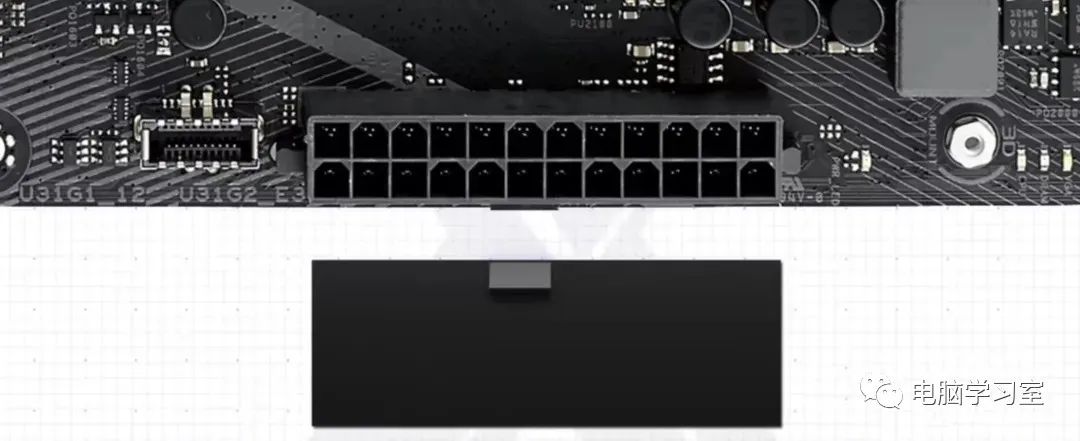
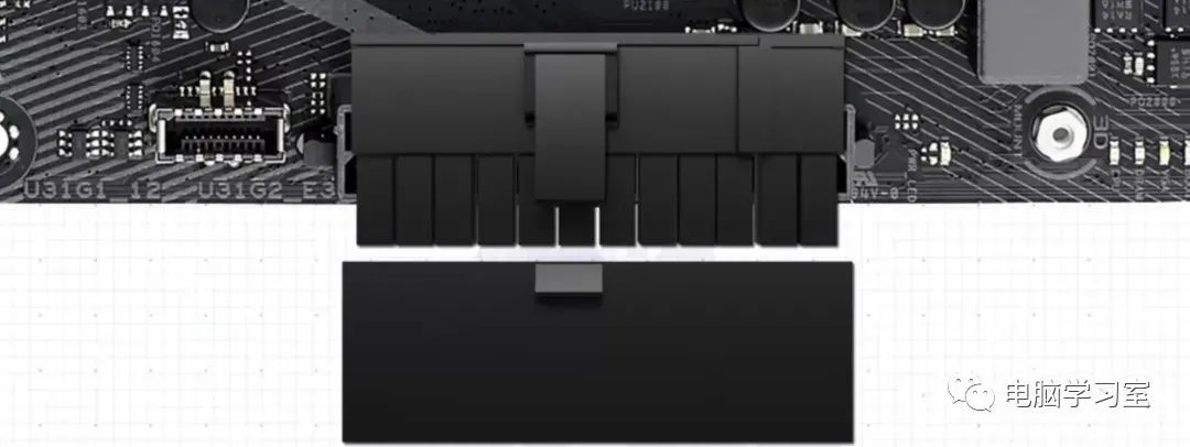
When we insert this power interface, you will find a small notch on the motherboard interface that aligns with the hook of the plug, allowing you to connect the ATX power interface.
2. CPU Power Interface:
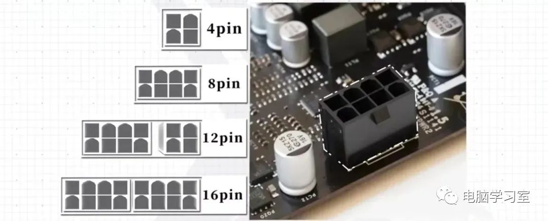
CPU power interface
Another interface on the motherboard is a 4 Pin, 8 Pin, 12 Pin, or 16 Pin interface, which provides power to the CPU. Find the connector labeled CPU on the power supply and connect it in the same way as the ATX power interface.
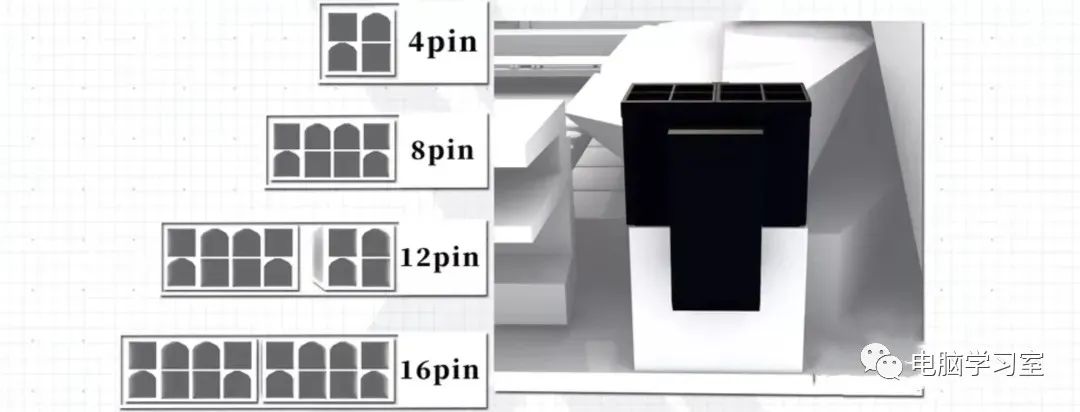
3. Graphics Card Power Interface:
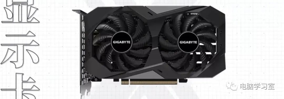
Graphics Card
The graphics card, commonly known as the GPU. Typically, it requires a 6 Pin or 8 Pin power connection. Taking the power connector here as an example, you can see that the connector can be a 6 Pin connector or can be combined into an 8 Pin connector. Some graphics cards do not require additional connections.
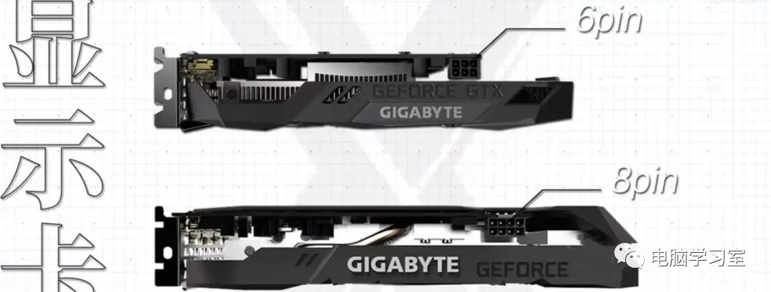
Graphics card power interface

6 Pin or 8 Pin
4. Hard Drive, Case Fan, and LED Strip Interfaces:

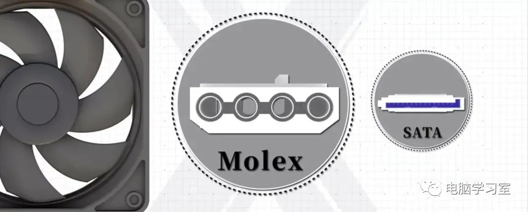
To power other devices, the power supply is equipped with multiple molex and sata power cables. The Molex connector has four pins, while the SATA connector has 15 pins.

More pins in SATA are designed to support hot-swappable devices and other additional features.
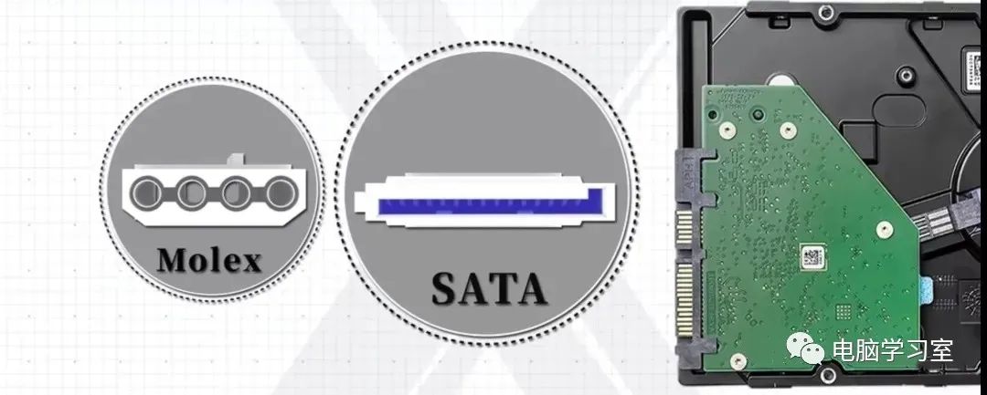
The SATA connector is set to an L shape, and Molex is also designed to be inserted in only one way. However, SATA connectors are mainly used forSATA hard drives, while Molex connectors were originally used for hard drives but are now used for other devices such ascase fans and LED strips.
5. CPU and Case Fan Interfaces:
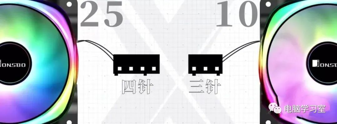
CPU and case fans. This uses 3 Pin and 4 Pin connectors. You can plug either into the same pins on the motherboard.
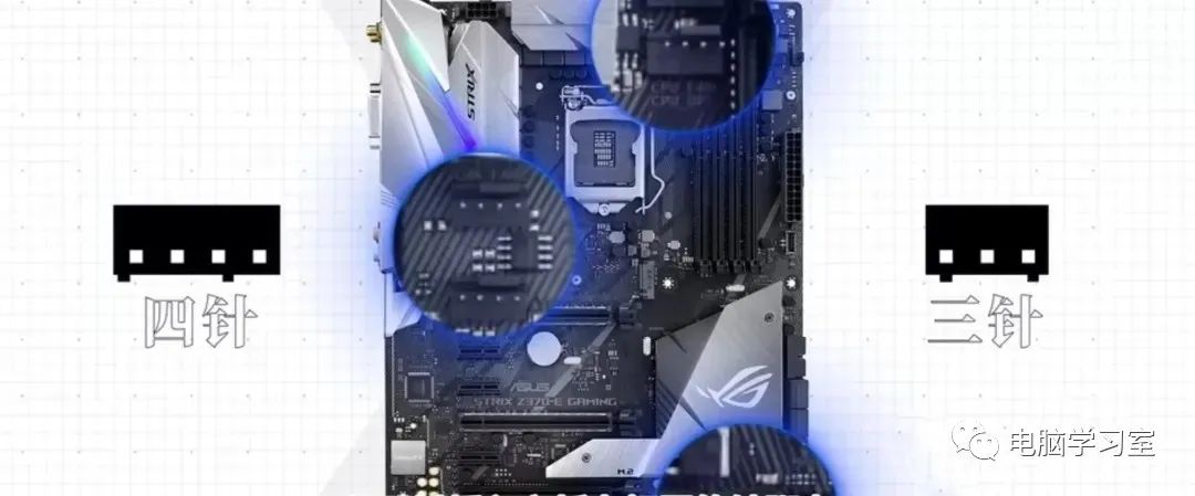
When inserting these pins, be sure to check the printed labels on the motherboard to understand which plug it is.

It is best not to connect the CPU fan to the case fan pins, as this will cause the fan to be misreported to the motherboard.

This will cause it to display an incorrect fan speed in any monitoring software. If the computer tries to change the fan speed, it will result in changing the wrong fan speed.

The additional fourth wire on the fan is for pulse-width modulation or PWM. This essentially means that the speed of the fan is controlled by the fourth wire.
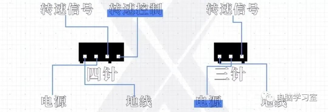
In 3 pin fans, the speed of the fan is controlled by the power supply, while in 4 pin fans, the speed is controlled by changing the signal in the fourth wire.
This raises the question, which one will you use?
4 pin fans tend to be more expensive, and another major difference is that since the voltage entering the fan does not change, if the fan has LED lights, they will not be affected. LED lights are usually not used in 3 pin fans because the changing voltage causes the LED lights to dim and brighten according to the fan’s speed.
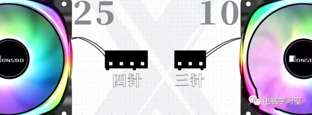
The motherboard typically supports both 3 pin and 4 pin fans, so it doesn’t matter which one you use.
6. Front Panel Connectors:
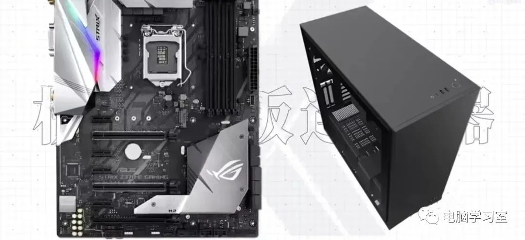
The indicator lights and buttons of the case connect to the motherboard. On many motherboards, you will find a place on the motherboard with these connectors, and next to the pins, there will be printed labels indicating what each pin is for.


You can also check the motherboard manual. Each motherboard manufacturer generally has similar pin parameters when producing motherboards, but there are also differences.

Here you will see that there are two pins for the power LED. If you find that you plugged it in incorrectly, don’t worry, on your case front panel connector, the incorrect connection of anything will not cause any damage; it just won’t work. As shown below:

The next two pins are for the power switch, which can be plugged in either way, as shown below:
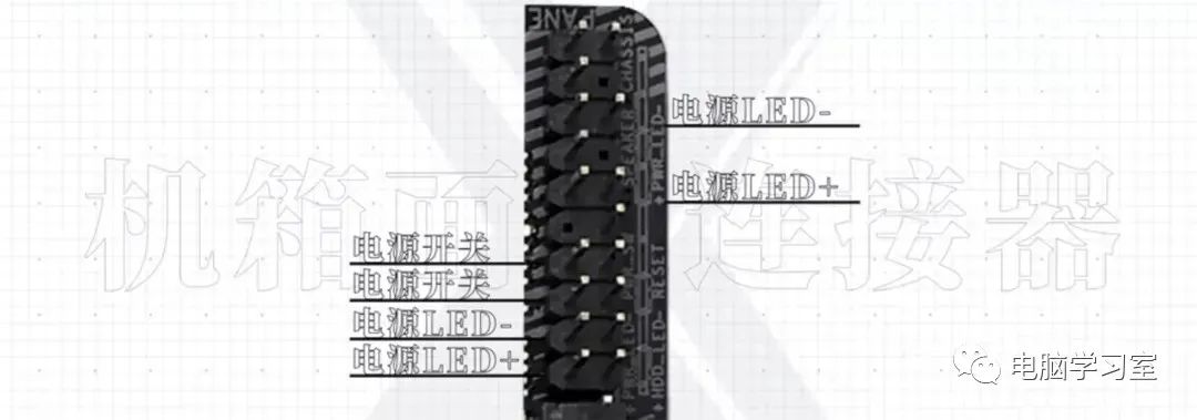
The next two pins are for the hard drive LED, which will light up when any storage device on the computer is active. Like the power LED, if the connection is incorrect, the LED will not work but will not damage anything. As shown below:
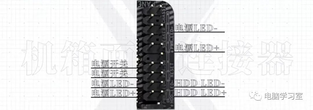
The next two pins are for the reset switch. Like the power switch, it is just a switch, so it doesn’t matter if you connect the positive and negative terminals incorrectly. These are standard connectors that you can find on most motherboards. Of course, some motherboards support certain functions while others do not. As shown below:

What you connect and do not connect depends on you. In fact, you only need to connect the power switch; all other connectors are optional.
Depending on the functions supported by the computer case, different cases will have different interfaces. Their connectors and wiring will also differ. They will have labels on the connectors.
7. USB and Type-C Connectors:

Common connector types also include USB, which are usually located at the front or top of the computer case.
In this specific instance, the front of the computer case has one USB 3, one USB 2 port, and one Type-C port. As shown below:

Inside the case, there are USB 3 wires, USB 2 wires, and Type-C wires. The USB 3 wire is blue. The USB 2 and Type ports are black.

8. Audio Interface Connectors:

And case exterior connectors, most computer cases have headphone and microphone jacks. To connect these two jacks to the motherboard, you must have an HD Audio connector, which plugs directly into the motherboard.
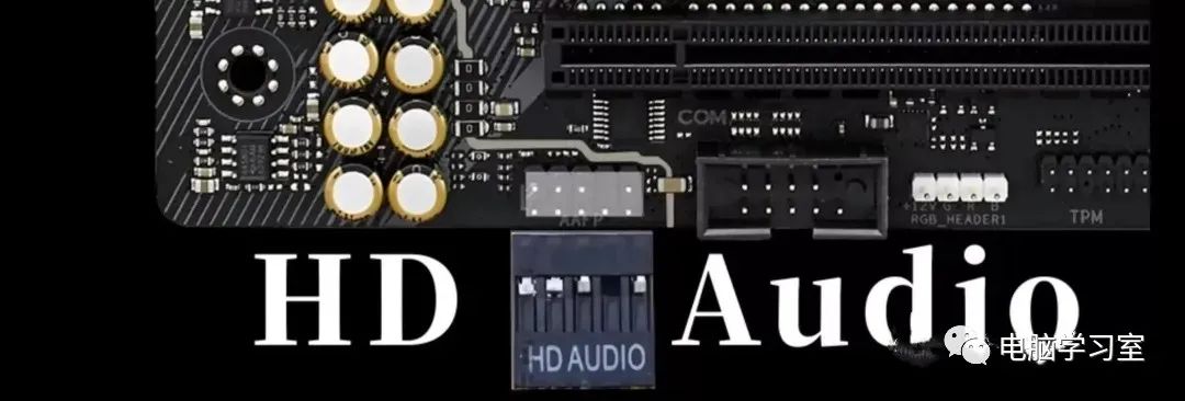
9. LED Key:

In addition to these, there is also an LED key, which can be seen in some more expensive cases. Its wire has two pins and is generally plugged into the RGB control box.
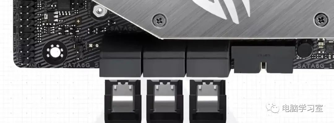
SATA connectors come in different quantities on different motherboards. We generally now have black interfaces, but in some cases, they do not have the same functions, such as RAID functionality.
10. M.2 Solid State Drive Slot:
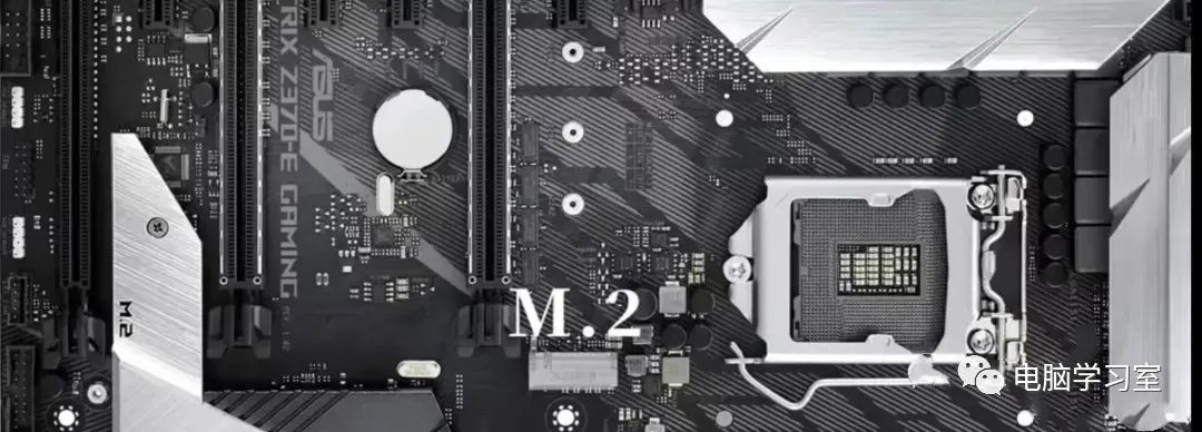
The M.2 expansion card is installed inside the motherboard. The M.2 device is inserted into the slot with its gold finger section, pushed down into the slot, and then secured with a screw.

Some now come with heat sinks.
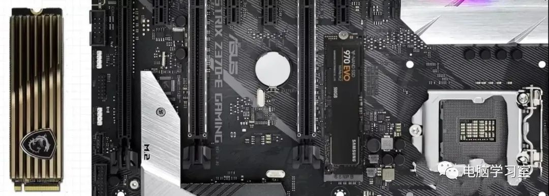
M.2 slots support PCI Express and SATA devices.
11. BIOS on the Motherboard:
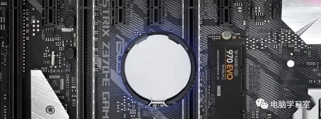
All motherboards will have BIOS functionality, and BIOS settings are stored on the motherboard. Damaged settings may prevent the computer from starting. To clear the settings, the motherboard will have a clear CMOS jumper. On older motherboards, there are usually three pins, while on newer motherboards, there are usually two pins.
In any case, if the pins are shorted at boot, all BIOS settings will be cleared.
12. TPM on the Motherboard:
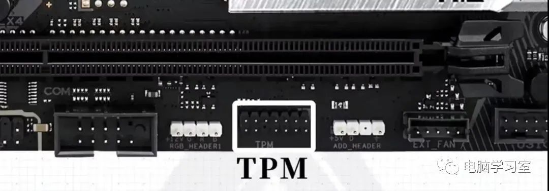
Your motherboard may not have this connector; generally, more expensive motherboards will have this connector.
TPM is a chip that contains encryption keys and other encryption-related functions, used to securely store these keys for functions like disk encryption and platform integrity.
Platform integrity is used in secure boot systems to check if the computer has been tampered with. Different motherboards will have different TPM connectors. Usually, different manufacturers consider their TPM connectors to be the same across all motherboards. No examples will be provided here.
Summary:
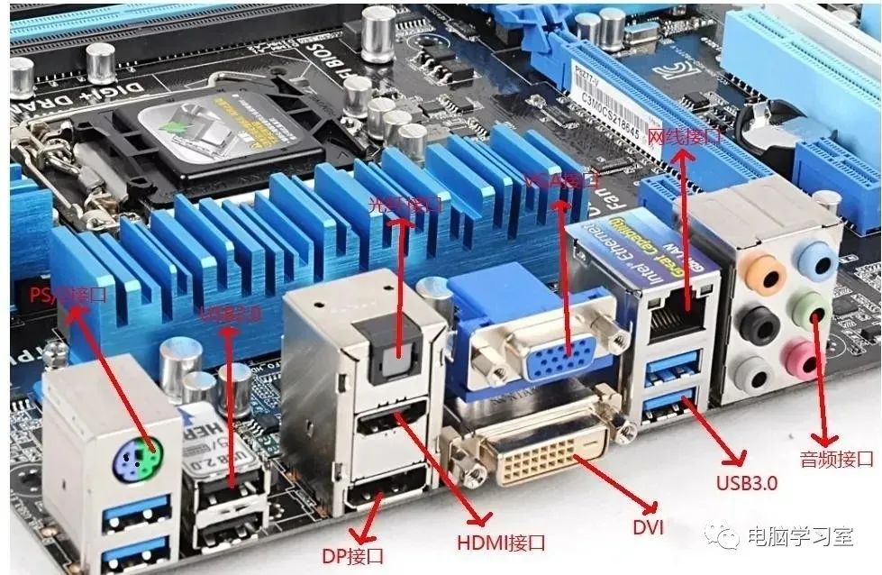
If you encounter problems when inserting connectors, please check the plugs and connectors. Generally, issues arise from missing or misaligned pins; just align these with the connector box plugs.
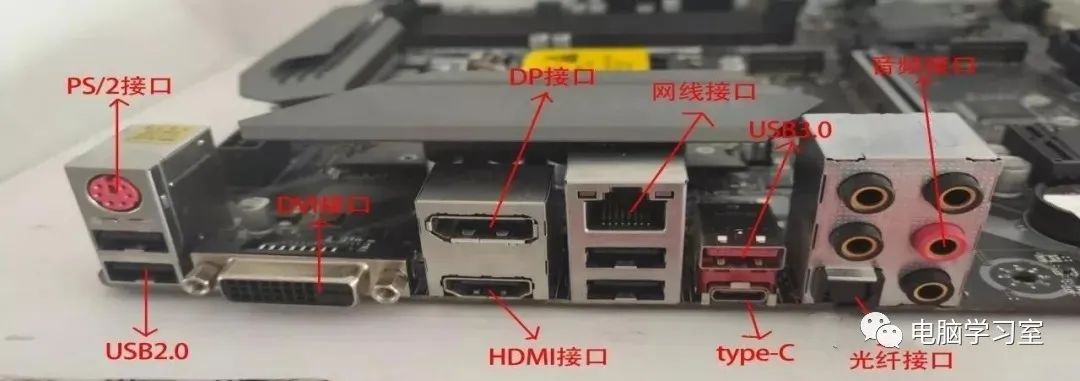
If you cannot find something on the motherboard, please refer to the manual. All motherboard manuals have a chart showing the location of everything; sometimes they can be difficult to find as many of these titles look very similar.
Previous articles: 👇
Share four methods to convert images to Excel, no more manual data entry!
Recommend seven useful USB and TF flash drive repair tools (with download links)
Recommend a very practical desktop enhancement tool~
Meeting is fate; if this helps you, feel free to follow and let’s learn together!