Introduction
In circuit design, neglecting ESD protection and isolation design to reduce costs can lead to serious consequences. This article will explore circuit issues caused by improper component addition and provide practical solutions to ensure the reliability and stability of circuit design.
-
If the added component affects circuit timing, it is best not to add such devices. -
Adding ESD protection devices on the bus clock signal line without proper capacitance control can distort the clock signal waveform, affecting normal communication; -
Adding a 22Ω resistor at the bus source end is a common design method, but the overall bus circuit must be considered. If a 22Ω resistor is already placed on the core board, there is no need to add another in series on the bottom board, or it may cause abnormal operation.
 Boot Phase Flicker
1. Phenomenon Description
The device exhibits flickering during the BootLoader and kernel stages after power on.
Starting from the software side, delaying the backlight did not completely solve the issue. Observing with an oscilloscope, there was a noticeable delay in the backlight control section.
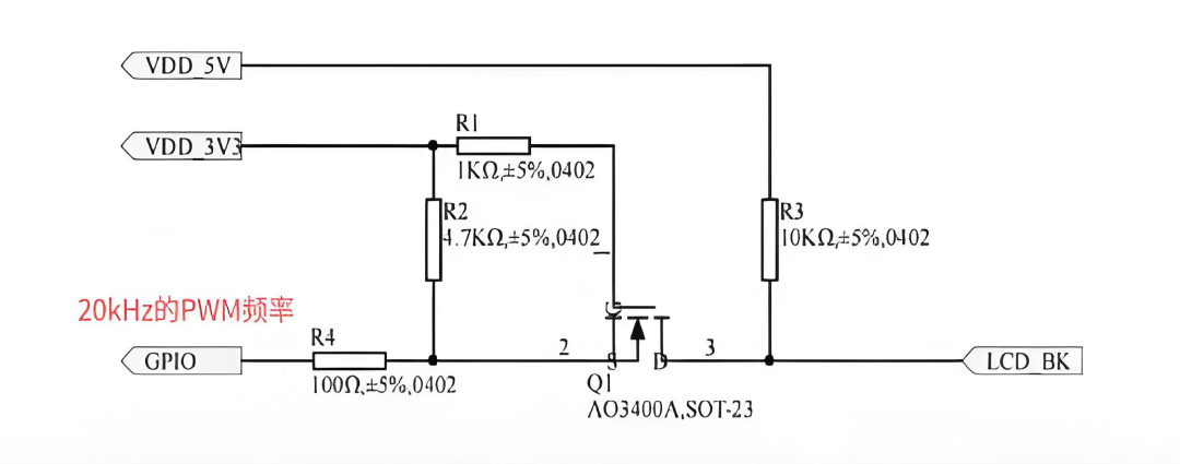
Next, analyzing from the hardware perspective, the backlight control circuit of the device is shown in Figure 1. Observing with an oscilloscope, when the device powers on, the LCD_BK pin has a high-level pulse, then maintains a low level, and finally transitions to a 20KHz PWM wave.
2. Analysis Process
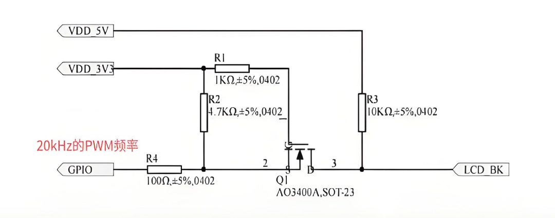
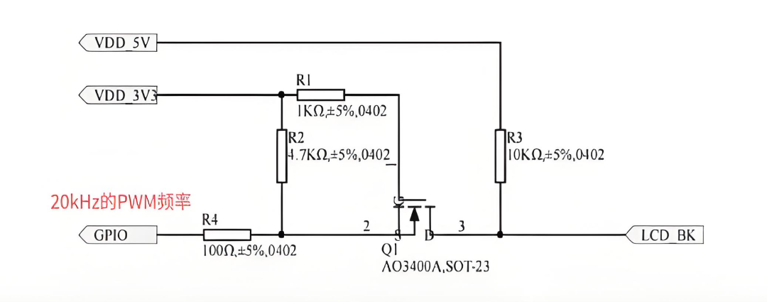
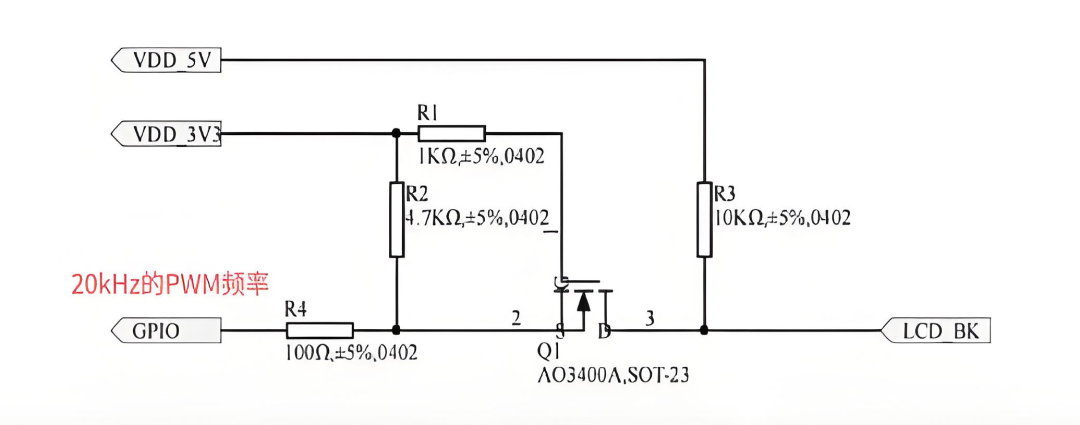
Based on the above phenomena, it can be generally determined to be a power-on timing issue. Measurement shows that VDD_5V powers on earlier than VDD_3V3. When VDD_5V powers on, VDD_3V3 is not powered, the system does not start, and the GPIO is in a high state, so the levels of pins 1 and 2 of Q1 are the same, keeping Q1 off. The LCD_BK signal is pulled high by R3, causing the backlight to turn on, and when the system starts, the GPIO outputs a low level, controlling the backlight to turn off, resulting in the flickering phenomenon.
Checking the backlight driver chip manual, the enable pin high-level threshold is 1.5V, as shown in Figure 2. No level conversion is needed; component Q1 is unnecessary, and 3.3V GPIO can drive it directly.
3. Solutions
 TF Card Not Recognized
1. Phenomenon Description
This phenomenon is common when all signal lines of the TF card are equipped with ESD protection devices, with the common issue being incorrect ESD device selection.
Taking the schematic in Figure 3 as an example for analysis.

SD2.0 requires the parasitic capacitance of ESD devices to be less than 9pF. First, check the datasheet of the ESD device (PESD3V3L4UG) and find that its parasitic capacitance can reach up to 28pF (see Figure 4), exceeding the requirement for SD2.0.
 Ethernet Matching Resistor
There is already a 22Ω source resistor on the Ethernet TX_CLK signal line of the core board, and the customer added a 22Ω matching resistor on the bottom board, causing unstable Ethernet communication.
Inserting the same core board into the evaluation board shows normal Ethernet communication, indicating the bottom board is the cause. Checking the schematic of the bottom board’s Ethernet circuit reveals that the TX_CLK pin is connected in series with a 22Ω matching resistor. The Ethernet reference circuit provided by Zhiyuan Electronics does not include a matching resistor, indicating that the user did not design according to the reference circuit.

3. Solutions
Replace the 22Ω resistor on the bottom board with a 0Ω resistor for normal Ethernet communication.
Pay attention to impedance matching for the data lines and control signals of the Ethernet PHY and processor end to avoid signal reflection. It is generally recommended to connect a 22~33Ω resistor in series at the source end in schematic design. However, if the core board already has a matching resistor connected in series at the source end, there is no need to add another matching resistor when designing the bottom board. When developing new products using the core board, it is advisable to refer to the official hardware design reference circuit from Zhiyuan Electronics.
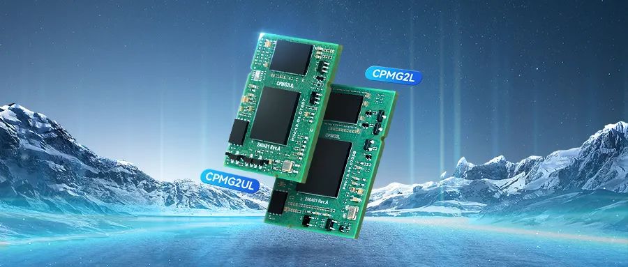
ZLG Innovative CPM Core Board
-
RZ/G2UL, RZ/G2L Processor
-
1.0/1.2GHz Main Frequency
-
Cortex®-A55+Cortex®-M33
Reference Price: Starting from 99 yuan
Click to Purchase


