Did you know? In automobiles, communication between multiple control units is actually achieved by connecting each control unit to these twoCAN buses, enabling information sharing among multiple control units…
What is CAN-BUS used for?
CAN-BUS, or CAN bus technology, stands for “Controller Area Network-BUS”. This bus technology was originally used for communication in electronic systems of aircraft, tanks, and other military equipment. The application of this technology in civilian vehicles originated in Europe, where it is used for transmitting data from various sensors in the vehicle.
Today’s vehicles have an increasing number of electronic control systems, such as electronic fuel injection systems, ABS systems, airbag systems, power windows, active suspension, and more. Various sensors distributed throughout the vehicle continuously monitor the vehicle’s status information and send this information to the corresponding control units.
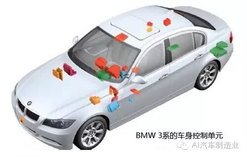 Distribution diagram of various control units in the vehicle
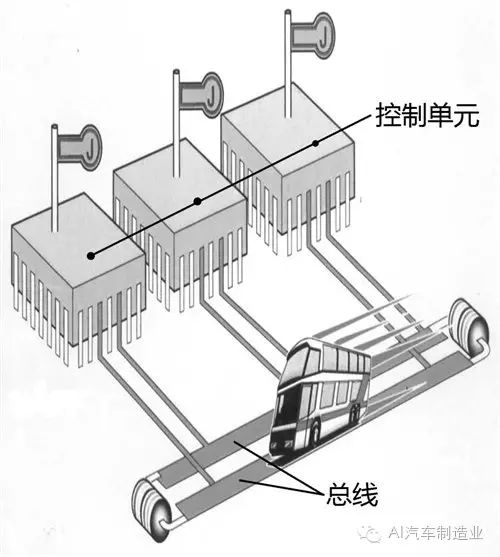
From the above diagram, we can see that as vehicles become more advanced, the number of control units in the vehicle increases. Each control unit can be viewed as an independent computer that can receive information, process and analyze various data, and then issue commands. For example, the engine control unit receives information from the intake pressure sensor, engine temperature sensor, throttle position sensor, engine speed sensor, etc. After analysis and processing, it sends corresponding commands to control the fuel injector’s fuel amount, ignition timing, and so on. The working principles of other control units are similar. Here, we can make an analogy: the various control units in the vehicle are like managers of different departments in a company, each receiving work reports from their department’s employees, making decisions after analysis, and instructing their employees to execute tasks.
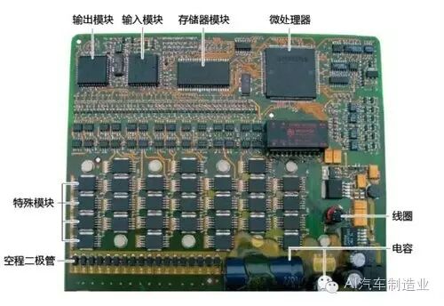 Control unit
The control units in the vehicle do not operate independently; they work as a whole and require information sharing. This raises the issue of information transmission. For example, the engine speed and throttle position signals from the engine control unit also need to be transmitted to the automatic transmission control unit, which will then issue commands for upshifting and downshifting. So how do these two control units communicate?
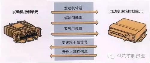 Each piece of information is exchanged through its own independent data line
Currently, there are two forms of information transmission used in vehicles: the first is that each piece of information is exchanged through its own independent data line; the second method is that all information between control units is exchanged through two data lines, which are also called CAN data buses.
The first method, where each piece of information is exchanged through its own independent data line, means that if there are 5 types of information to be transmitted between two control units, then 5 independent data lines are required. In other words, the more types of information there are, the more data lines and control unit pins will increase accordingly. These complex and numerous wiring harnesses undoubtedly increase the weight of the vehicle and pose certain difficulties for the overall wiring of the vehicle.
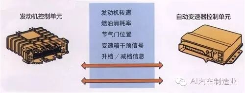 All information is exchanged through two data lines
The second method is that all information between control units is exchanged through two data lines ( CAN data bus). With this method, all information, regardless of its size, can be transmitted through these two data lines, which significantly improves the overall system’s operational efficiency. A common computer keyboard has 104 keys but can issue hundreds of different commands, yet the data connection line between the keyboard and the computer host only has 7 wires. The keyboard relies on different coded signals on these 7 data connection lines to transmit information. The principle of the CAN data bus is similar. This change from a dedicated line for each use to a multi-use line can greatly reduce the number of wires in the vehicle and simplify the overall wiring.
Having understood that two control units exchange information through two data lines, we can extend this concept: communication between multiple control units is essentially achieved by connecting each control unit to these two CAN buses, enabling information sharing among multiple control units.
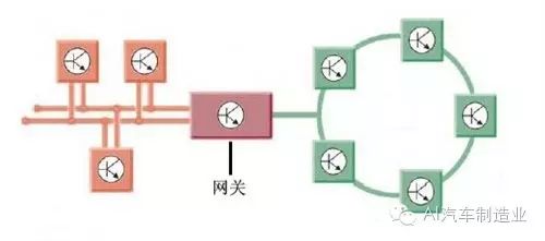
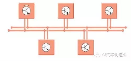 Information transmission among multiple control units
Currently, there are two main connection methods for the CAN bus in automobiles: one is the high-speed CAN bus used for the drive system, with a rate of up to 500kb/s, and the other is the low-speed CAN bus used for the body system, with a rate of 100kb/s. Of course, for mid to high-end cars, there are also buses for entertainment systems or intelligent communication systems, which have even higher transmission rates, exceeding 1Mb/s. The high-speed CAN bus mainly connects the engine control unit, ABS control unit, airbag control unit, instrument cluster, and other systems directly related to vehicle operation. These systems require a high volume of information transmission and have high-speed requirements, thus necessitating the use of a high-speed CAN bus. The body system’s CAN bus mainly connects systems like central locking, power windows, mirrors, and interior lighting, which do not have high data transmission rate requirements.
This is like two vehicles trying to reach the same destination; a sedan can choose to take the highway because only the highway can leverage the sedan’s speed advantage, saving more time. In contrast, a truck, being slower, only needs to take regular roads, as taking the highway does not showcase its speed advantage and may incur more costs.
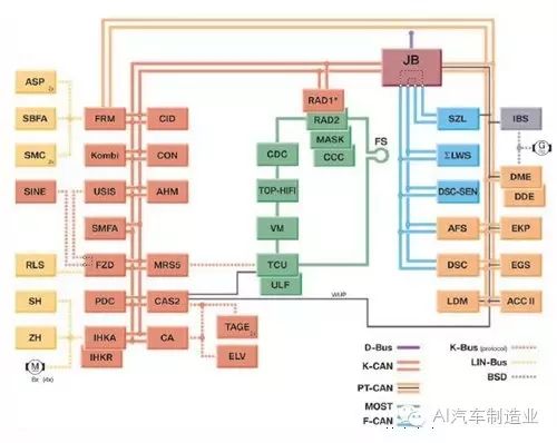 Different systems use different speed buses
In the above image, control units of the same color use a specific speed bus system. This method of using different CAN buses according to their respective needs optimizes resources and reduces the overall cost of the vehicle. Additionally, there is a sub-bus system that mainly connects electrical switches and control units or sensors and control units. For example, the button for electric windows uses a sub-bus system to connect to the corresponding control unit. This sub-bus system mainly transmits relatively small amounts of data within the system, and of course, its data transmission rate is lower, using a single-wire system.
The bus system, also known as CAN-BUS, is actually similar to the working principle of a public bus in operation. Each station corresponds to a control unit, while the route is the CAN bus. The data transmitted on the CAN bus is akin to passengers on a bus. When a control unit receives information from a sensor responsible for sending data to it, it analyzes and processes this information, takes appropriate actions, and sends this information onto the bus system. This way, the information is transmitted on the bus system, and each control unit connected to the bus system receives this information. If the information is useful to it, it will store it; if not, it will ignore it.
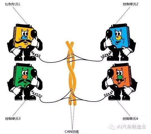
The entire principle is very similar to a conference call, where one phone user (control unit) “speaks” data into the network, and other users “listen” to this data. Users interested in this data will utilize it, while others will choose to ignore it.
Different bus systems exchange and transmit information through gateways
As mentioned earlier, different bus systems have different transmission rates, which can cause communication issues between different bus systems. This is akin to a United Nations conference where each member country speaks its own language; to understand each other, a translator proficient in all languages is needed to facilitate information transmission. An important control unit in the vehicle network system is the “gateway,” which connects multiple different CAN data buses and acts as a translator during data transmission.
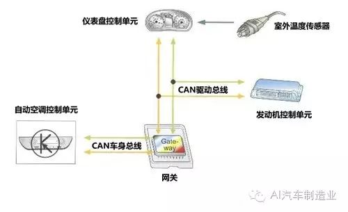 The gateway acts as a “translator” in the vehicle network
For example, an outdoor temperature sensor belonging to the drive bus system sends the detected temperature signal to the instrument panel control unit, which then sends this signal onto the drive bus system. This signal is collected by the engine control unit and is further transmitted to the body bus system through the gateway’s “translation”. The automatic air conditioning control unit belonging to the body bus system receives this signal and takes actions such as increasing cooling or reducing airflow. This process reflects the information sharing within the entire vehicle network.
Advantages of the CAN bus
Finally, let’s discuss the advantages of the CAN bus system:
① Higher data transmission speed compared to traditional wiring methods.
② Saves wiring harness compared to traditional wiring methods, reducing vehicle weight and optimizing vehicle wiring.
③ In a control unit connected via the CAN bus, if one unit fails, other control units can still send their data without being affected.
④ The CAN data bus is a dual-wire system; if one wire fails, the CAN system will switch to single-wire operation mode, improving the overall stability of the vehicle.
⑤ The dual wires of the CAN system are twisted together like a “twist tie” in practice, effectively preventing electromagnetic interference and radiation.
⑥ The CAN bus system enables richer body functions.
The CAN bus system greatly simplifies the layout of vehicle wiring, which can be reflected in the neat and organized layout of the engine compartment. While the body functions have increased, the wiring harness has been simplified, making maintenance more convenient. During use, if a component fails, it will automatically shut down its output function to prevent other components on the bus from being affected, thus improving the stability of the vehicle’s electronic control system to some extent. This complete network system, which connects various functional components, allows for information and data sharing throughout the vehicle, making the vehicle’s control more intelligent and precise. In fact, this technology has begun to enter ordinary family cars, no longer exclusive to luxury vehicles. (Source: Auto Home)
Largest Automotive Repair Case Database
Only Practical Content
Automotive Repair Case: qixiuanli
Complex Issues | Timing Adjustment | Automotive Repair Techniques | Maintenance Reset