In PCB design, electronic circuit simulation technology is one of the essential skills that learners and professionals in related fields must master, and it has many advantages:
1. Electronic circuit simulation software generally has a vast and comprehensive library of electronic components and advanced virtual instruments, making simulation and testing very convenient;
2. The connection of simulated circuits is simple, quick, and intelligent; there is no need for soldering, and there is no concern about damage when using instruments for debugging; this greatly reduces design time and costs;
3. Electronic circuit simulation software can perform various accurate and complex circuit analyses.
With the continuous development of electronic circuit simulation technology, many companies have launched various advanced and powerful simulation software. Since they can compete in the market, they must have their strengths and weaknesses in certain aspects. Below is a comparison of the advantages and disadvantages of several mainstream electronic circuit simulation software.
(1) Multisim
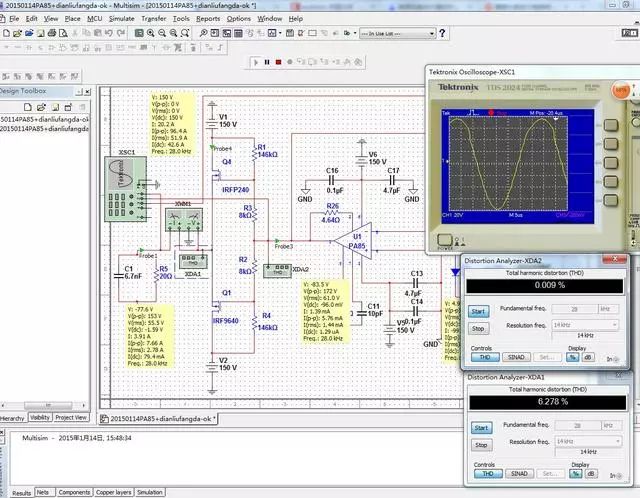
In the virtual simulation of complex circuits in analog and digital electronics, Multisim is undoubtedly the leader. It has extremely realistic virtual instruments, and both the appearance of the interface and the internal functions have reached the highest level. It has a professional interface and classification, powerful and complex functions, and is extremely accurate in data calculations. When we participate in electronic competitions, especially in simulation-related topics, the simulation software we use the most is Multisim. Additionally, Multisim supports not only MCUs but also assembly language and C language for programming microcontrollers, and it has a matching PCB layout software, NI Ultiboard10, which provides a complete service from circuit design to board layout.
The disadvantage of Multisim is that the software is too large, and its support for MCUs is insufficient; the additional functions like PCB layout do not compare to other specialized software.
(2) Tina
Tina has a simple and intuitive interface, with a moderate number of components, but excellent classification, and the components from TI are the most comprehensive. During competitions, when we often use TI components, we switch to Tina for simulation when we cannot find the corresponding component in Multisim.
The disadvantage of Tina is its relatively limited functionality and less support for components outside of TI.
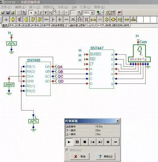
(3) Proteus
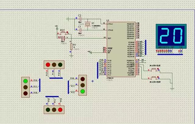
Proteus is an integrated software for circuit simulation, PCB design, and microcontroller simulation. It contains a large number of components based on real environments, supports many mainstream microcontroller models and general peripheral models, and provides excellent real-time display effects. Its dynamic simulation is based on frames and animations, providing better visual effects. Proteus supports the editing/compiling/source-level simulation of microcontroller assembly language, comes with compilers for 8051, AVR, and PIC, and can integrate with third-party environments (such as IAR, Keil, and Hitech) for high-level language source-level simulation and debugging.
The disadvantage of Proteus is its insufficient data calculation capabilities for circuits.
(4) Cadence
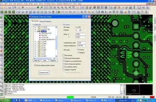
Cadence has acquired and integrated the functionalities of Pspice, covering the entire process of electronic design, including system-level design, functional verification, IC synthesis and layout, analog, mixed-signal, and RF IC design, fully customized integrated circuit design, IC physical verification, PCB design, and hardware simulation modeling. Cadence is the preferred choice for complex EDA designs.
The disadvantage of Cadence is that its operation is relatively complex, making it more suitable for the development of complex boards.
(5) Matlab Simulation Tool Simulink
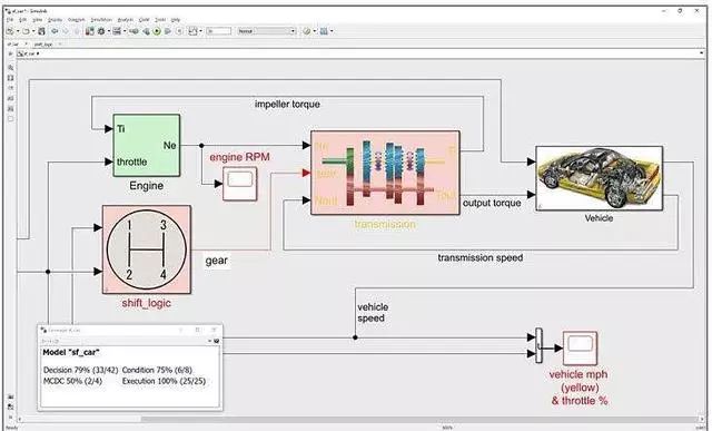
Currently, the large-scale scientific computing and simulation software Matlab has been equipped with a power system toolbox, allowing Matlab to be used for power electronics simulation. The PowerSystem simulation is based on Matlab’s Simulink graphical environment, making it as convenient as PSpice. Simulink is one of the most important functional modules in the Matlab package, serving as an interactive, modular modeling and dynamic analysis system for simulation. In the field of power electronics, Simulink is typically used to establish simplified models of power electronic devices (such as fundamental frequency models) and connect them into systems for direct controller design and simulation. Simulink provides excellent support for C language code and can operate in both interactive graphical environments and batch modes using Matlab command language.
Matlab serves as a simulation tool based on idealized power components and functional modules. Its powerful mathematical computation capabilities make the control functions of PowerSystem excellent, especially when using other related toolboxes, circuits can achieve detailed control without requiring significant effort. Another benefit of using Matlab is its highly efficient and precise data processing, fast execution speed, and excellent compatibility of data formats, facilitating post-processing and analysis of data, particularly in the study and analysis of control characteristics.
The disadvantage of Matlab is that the current PowerSystem is based on models of general circuit components and mathematical modules (such as transfer functions), which differ from the actual component parameters, leading to simulation results that are somewhat distant from actual circuits. The reference significance of its results primarily reflects the overall circuit and system. The switches and control units largely use ideal components, where the switch controller can be directly connected to the switch without considering level shifts. It essentially ignores the transient process description of actual switches. In summary, Matlab simulates ideal models and cannot consider situations under non-ideal conditions.
(6) Altium Designer
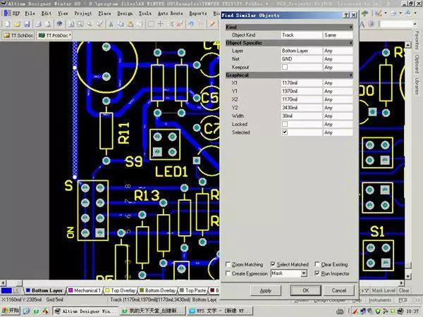
Altium Designer not only fully inherits the features and advantages of previous versions, including Protel 99SE and Protel DXP, but also adds many improvements and high-end features. The platform broadens the traditional interface of board-level design and fully integrates FPGA design functions and SOPC design implementation functions, allowing engineering designers to integrate FPGA with PCB design and embedded design in system design.
Altium Designer is mainly used for schematic design, circuit simulation, and PCB layout editing, and it is essential software for electronic competitions.
The disadvantage of Altium Designer is that it is not as capable as Cadence for complex board design.
Above is the comparison of the advantages and disadvantages of several mainstream electronic circuit simulation software in PCB design.

The only certified high-speed PCB design examination certification/training employment platform jointly recognized by the Ministry of Human Resources and Social Security and the China Association of Employment Services
Authoritative certification, a wealth of cases, high salary offers, and a smooth promotion path, just visit Quick PCB (www.eqpcb.com)~
The most influential high-speed PCB design B2C platform in China
Over 1,000 companies can publish demands with one click, and over 5,000 layout engineers can easily take orders~
0755-84719081
Follow Quick PCB Academy for the latest industry information/technical insights~