When I was developing products, I used to scoff at the ESP32, thinking it was just a toy, lacking reliability, ease of use, and anti-interference capabilities for actual products. However, later on, when some of Xiaomi’s smart home products began to adopt it in large quantities, my perspective changed slightly. Nevertheless, I still wouldn’t use it in my products.
However, the cost-performance ratio and playability of the ESP32 are indeed impressive, so much so that I hesitated to try it, sticking to my familiar “32” series experiences, as it seemed more complex than microcontrollers.
Unable to resist its high cost-performance and playability, especially with the rise of AI, I had to give it a try.
I have never been a good student, and diligently studying data sheets has never been my style, so I decided to dive right in. After all, Lichuang offers free PCB prototyping, and I had some old ICs on hand.
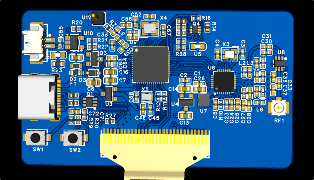
I directly replicated the official recommended minimal system design and added a PAN3029 wireless transceiver on the right side. As expected, I was like a master craftsman caught off guard.
After spending half a day soldering three pieces, with 0402 components that strained my eyes, I felt a sense of accomplishment when I powered it on. After two years of recovery, my hands are finally not so shaky. Soon, the USB on my computer popped up port 6.
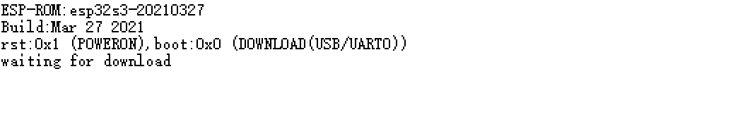
Speaking of the ESP32, it is indeed convenient; you can directly program it via the serial port, and it prints log information as soon as it powers on. As long as you pull down GPIO0 during power-up, the system will enter download mode. At least at this point, we can confirm that the board powers on without issues, the CP2102 is functioning, and serial communication is okay.
Next, I was stumped on how to develop. I had two choices: one was the IDF based on VS Code, and the other was the Arduino IDE. Since I had never used Arduino before and wanted to teach my child programming, I chose Arduino.
Click Follow and Star Eefocus
Scan to reply with the keyword “Electronic Technology” to join the industry group and receive reports.
In the Arduino IDE, we need to install the ESP32 development board, which can be searched directly from the board manager.
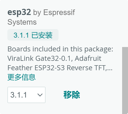
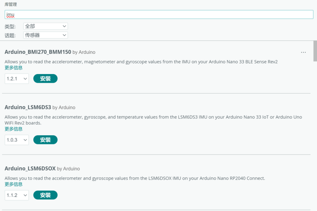
I chose the official one, and I must say, this is much more convenient than setting up the environment for the “32” series. There are also some STM32 development boards available here that I need to try out when I have time. In addition, there are many software libraries, and I briefly browsed through them; they are very comprehensive.
I randomly selected an ESP32 S3 board from the development board and found the classic blink project, compiled, and downloaded it in one go…
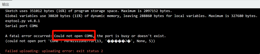
Hmm? The serial port couldn’t be opened; it was occupied. I closed other serial debugging tools and tried again.
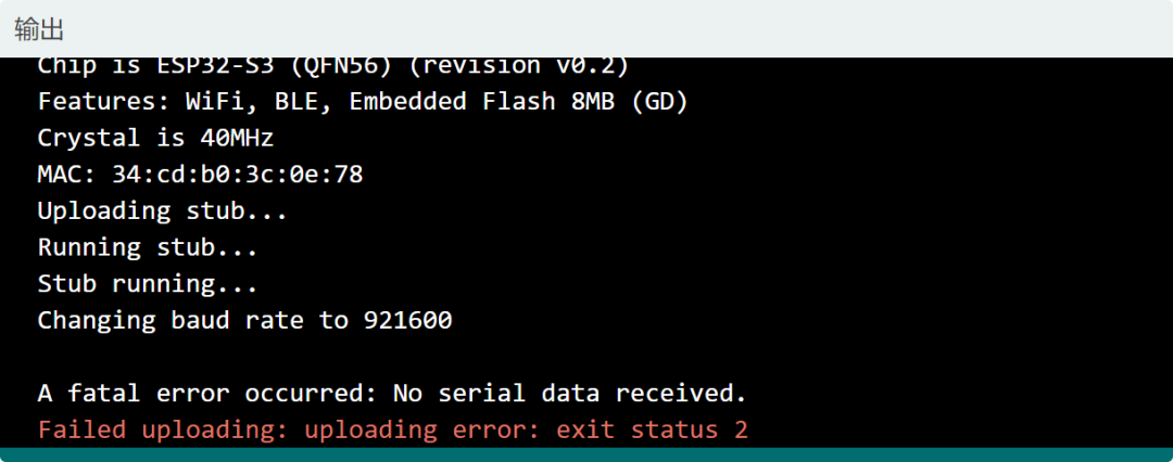
It seems that completing everything in one go is quite difficult. The log here shows that no serial data was received. The information above indicates that it changed the baud rate to 921600. Could it be that the speed is too fast? Or was the modification unsuccessful?
From the chip model, crystal frequency, and MAC address above, the serial transmission and reception must be normal, so I can only suspect that the changing of the baud rate to 921600 has issues. I can lower this baud rate since the default 115200 can read the MAC address and other information, so using 115200 should be fine.
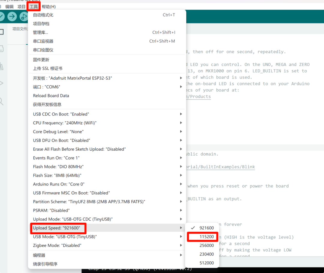
There are many options to set here, and I must clarify each one later. For now, I can’t worry about so much. Compile, download…
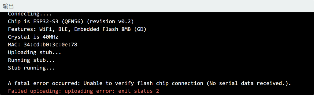
There is still an error; this time it says it cannot verify the Flash connection, and the message in parentheses is quite strange. It still shows no serial data received. But earlier, I clearly read the MAC address and other information.
So I Googled “No serial data received,” asked ChatGPT, and checked DeepSeek. The answers were comprehensive, suggesting I check the power supply, wiring, and Flash.
I followed several posts on Google to verify; the power measurement was fine, and I added several capacitors at the power pins, both large and small, but it didn’t work.
I also removed the ESP32 chip, shorted TX and RX, and verified that the CP2102 was functioning, able to send and receive.
For the “unable to verify flash chip connection” issue, I spent an hour checking posts. The problems encountered online varied widely; some said just changing the USB cable would solve it because a 4-pin USB power cable is needed, while others said the power supply must use LDO, not DCDC. These were all foreign posts, and it seems that those encountering issues abroad are mostly beginners.
It seems there are no shortcuts; I can only study the manual.
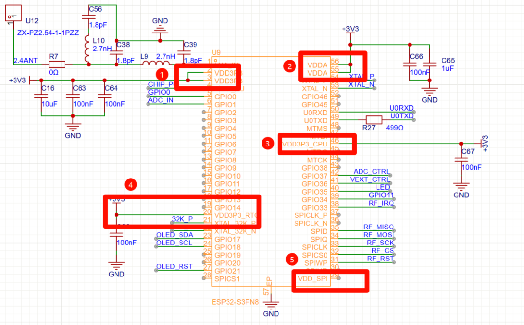
After repeatedly checking the power system, there are a total of five places related to power, and only the fifth place was left unconnected. This place is supposed to supply power when connecting to external Flash. It should be fine.
I also reviewed the logic of chip-pu and GPIO0 several times. My board can reset and enter download mode by pulling down GPIO0, so I don’t know what to suspect here.
It wasn’t until the end that I focused on my use of SPI. When I first drew the schematic, I only planned the lines according to the pin mapping table.
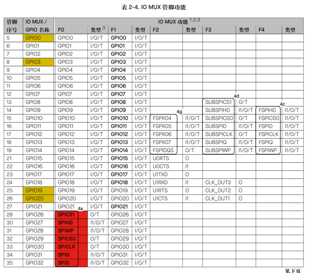
As shown in the figure above, for pins 28 to 35, their first function F0 is the default SPI connection to Flash, while F1 function mapping is just regular GPIO. I initially intended to use GPIO to simulate SPI.
Frustratingly, the official documentation states:
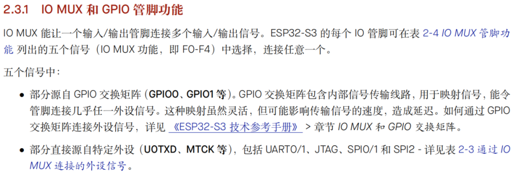
There was also a sentence in the official documentation that misled me.
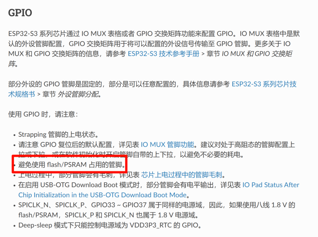
This should mean avoid instead of do not. I misunderstood it as try not to. It would have been better if they had just written do not. I assumed that IO mapping could be changed.
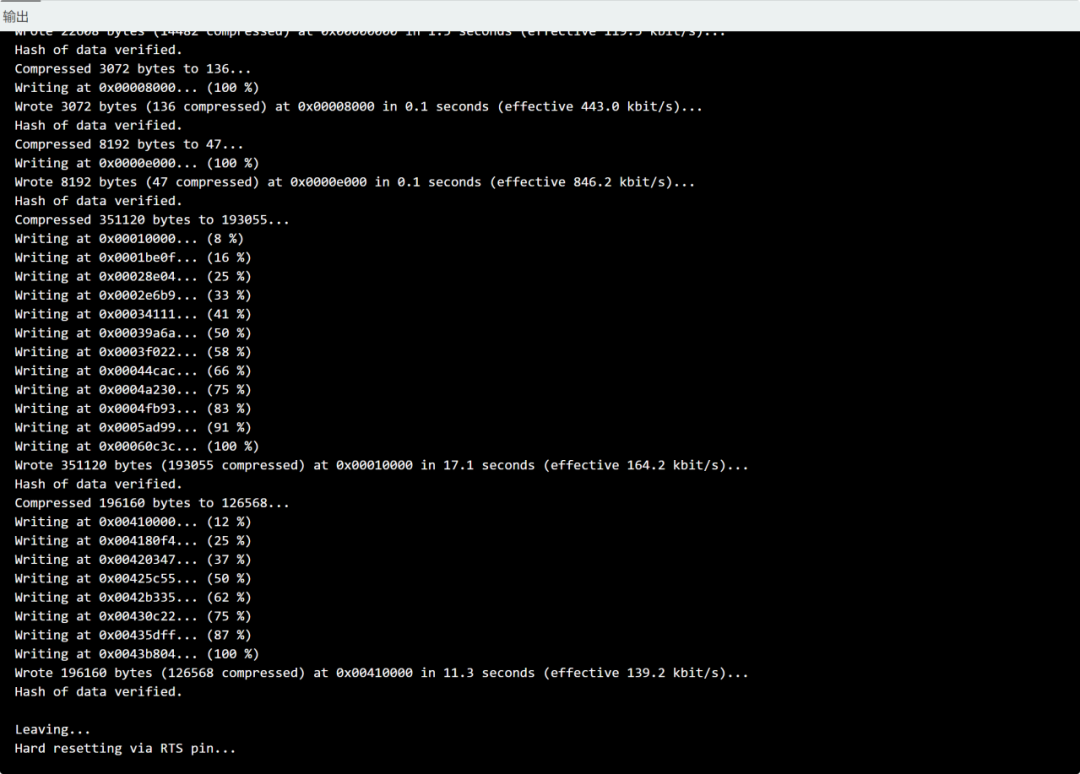
I immediately desoldered my RF chip for SPI communication, compiled, and downloaded.
END
Note: The cover image of this article is from Freepik, self-made by the author, and publicly available media, all authorized.
Welcome to leave comments and exchange in the comment area!

Industry Community