Fundamental Concepts of Communication
- Signal: The physical representation of information (voltage, current, light, radio waves).
- Transmission Medium: Wires (single wire, twisted pair, coaxial cable), PCB traces, optical fibers, air (wireless).
- Data Frame/Packet: The basic unit of structured transmission (start bit, address, data, control information, checksum, stop bit).
- Baud Rate: The number of signal changes per unit time.
- Bit Rate: The number of valid data bits transmitted per unit time (usually equal to the baud rate).
- Error Detection: Parity, checksum, cyclic redundancy check (CRC).
- Protocol Stack: A hierarchical abstraction of communication functions (physical layer, data link layer, application layer, etc. – simplified OSI model).
Synchronization vs. Asynchronization:
- Synchronization: Both communicating parties use a shared clock signal to coordinate data transmission (e.g., SPI, I2C).
- Asynchronization: Each communicating party uses its own clock, relying on start bits, stop bits, and baud rate agreements to synchronize (e.g., UART).
Serial vs. Parallel:
- Serial: Data bits are transmitted one after another on a single line (most embedded protocols).
- Parallel: Data bits are transmitted simultaneously on multiple lines (faster but requires more lines, less common in modern embedded systems).
Simplex, Half-Duplex, Full-Duplex:
- Simplex: Data can only be transmitted in one direction (e.g., broadcasting).
- Half-Duplex: Data can be transmitted in both directions, but not simultaneously (e.g., I2C, CAN).
- Full-Duplex: Data can be transmitted simultaneously in both directions (e.g., SPI, UART).
Master/Slave Mode vs. Peer-to-Peer Mode:
- Master/Slave: One master device controls communication and initiates requests; one or more slave devices respond.
- Peer-to-Peer: Devices can initiate communication equally (e.g., CAN).
1. UART / RS-232/RS-485
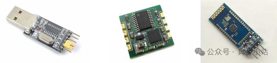
- UART: Universal Asynchronous Receiver/Transmitter
- Core Features: Asynchronous, serial, full-duplex (typically), point-to-point (standard UART).
- Advantages: Simple, extremely low cost (hardware is widely integrated), full-duplex, easy to implement and debug.
- Disadvantages: No addressing (not suitable for multiple devices), no hardware collision detection (requires software handling), poor anti-interference capability (TTL/RS-232), limited distance (RS-485 can be longer).
- Typical Applications: Debug output (Console), connecting PC and microcontroller, communicating with GPS/GPRS modules, simple communication between two microcontrollers. RS-485 is used for longer distance communication in industrial environments (multi-node).
- Key Concepts: Baud rate, frame format (data bits/stop bits/parity), flow control (RTS/CTS – optional).
Physical Layer:
- Voltage Standards: TTL (0-3.3V/5V), RS-232 (±3V to ±15V), RS-485 (differential ±1.5V to ±6V).
- Wiring: At least 2 wires (TX, RX), plus GND. RS-232 commonly uses DB9 connectors. RS-485 requires differential lines (A+, B-).
Data Link Layer:
- Frame Structure: Start bit (1 bit, Low) + Data bits (5-9 bits) + Optional parity bit (1 bit) + Stop bit (1, 1.5, 2 bits, High).
- No addressing mechanism: Physical point-to-point connection implies the communication object.
- No clock line: Synchronization relies on agreed baud rate, start bit, and stop bit.
- Error Detection: Parity (optional).
2. I2C / TWI
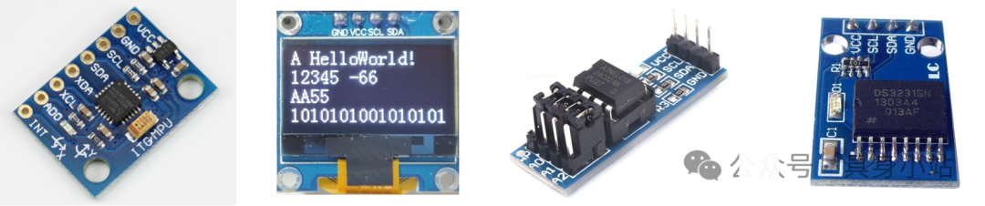
- I2C: Inter-Integrated Circuit
- TWI: Two-Wire Interface
- Core Features: Synchronous, serial, half-duplex, multi-master multi-slave (typically single master), address-based.
- Advantages: Very few pins (2 wires), supports multiple devices, supports multi-master (with arbitration), has hardware acknowledgment mechanism, moderate speed, widely supported.
- Disadvantages: Half-duplex (only one direction at a time), slower than SPI, bus capacitance and pull-up resistors limit maximum speed and number of devices, open-drain structure may slow rise time under high load.
- Typical Applications: Connecting low-speed peripherals: sensors (temperature, humidity, accelerometer), EEPROM, RTC, LCD controllers, I/O expanders, ADC/DAC.
- Key Concepts: 7/10-bit addressing, ACK/NACK, start/stop/repeated start conditions, clock stretching, open-drain/pull-up.
Physical Layer:
- Voltage Standards: Typically the logic levels of microcontrollers (3.3V/5V).
- Wiring: Only two wires needed
- SDA (Serial Data): Bi-directional data line.
- SCL (Serial Clock): Clock line generated by the master device.
- Open-drain/collector output: Requires pull-up resistor (Rp) to pull the bus high. Devices can only pull the bus low (line and logic).
Data Link Layer:
-
Frame Structure:
- Start Condition: SDA goes low when SCL is high.
- Address Frame: 7-bit or 10-bit slave device address + 1-bit read/write direction bit (R/W#).
- Data Frame: 8-bit data + 1-bit acknowledgment bit (ACK/NACK). ACK is pulled low by the receiver after the data.
- Stop Condition: SDA goes high when SCL is high.
- Repeated Start Condition: Initiating a new transmission without releasing the bus.
-
Addressing: Each slave device has a unique address (some addresses can be configured).
-
Arbitration: When multiple master devices attempt to start transmission simultaneously, arbitration occurs through line and logic (whoever sends 0 first wins).
-
Clock Stretching: Slave devices can pull SCL low to pause the master device’s clock while processing data (characteristic of low-speed slave devices).
-
Speed Modes: Standard (100 kbps), Fast (400 kbps), Fast-mode+ (1 Mbps), High-speed (3.4 Mbps).
3. SPI
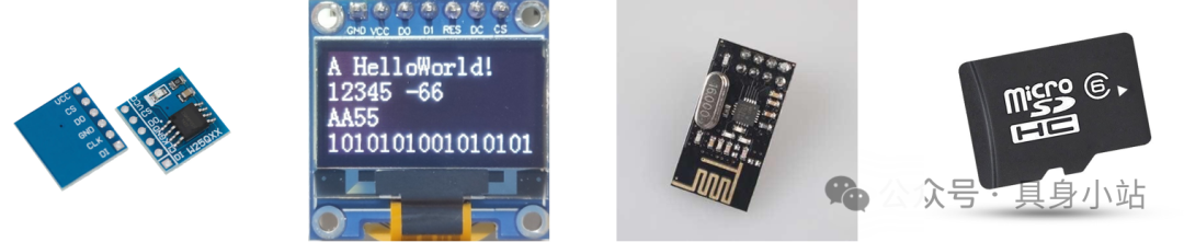
-
SPI: Serial Peripheral Interface
-
Core Features: Synchronous, serial, full-duplex (typically), master/slave mode, based on chip select.
-
Advantages: High speed (much faster than I2C/UART), full-duplex, simple and flexible protocol (no complex frame structure), strong driving capability (push-pull).
-
Disadvantages: Uses many pins (each additional slave device requires an extra SS line), does not support multi-master, no hardware error detection/acknowledgment, no bus arbitration.
-
Typical Applications: Connecting high-speed peripherals: SD cards, Flash memory, displays (TFT, OLED), high-speed ADC/DAC, Ethernet/WiFi modules, sensors (when high-speed reading is required).
-
Key Concepts: CPOL/CPHA (Mode 0-3), chip select (SS/CS), full-duplex, master/slave clock (SCLK).
Physical Layer:
- Voltage Standards: Typically the logic levels of microcontrollers (3.3V/5V).
- Wiring: At least 4 wires (full-duplex):
- SCLK (Serial Clock): Clock line generated by the master device.
- MOSI (Master Out Slave In): Master device output, slave device input.
- MISO (Master In Slave Out): Master device input, slave device output.
- SS/CS (Slave Select / Chip Select): Controlled by the master device, selects which slave device to activate (each slave device requires an independent SS line).
- Push-pull output: Strong driving capability, high speed.
Data Link Layer:
- Frame Structure: No strictly defined frame (start/stop). Data transmission occurs on clock edges.
- Addressing: Select slave devices through hardware chip select lines (SS/CS). No address byte.
- Clock Phase (CPHA) and Polarity (CPOL): Define on which edge of the clock data is sampled and output. There are 4 combination modes (Mode 0-3).
- Data Transmission: The master device sends data bits through MOSI under SCLK control while receiving data bits from the slave device through MISO (full-duplex).
- No hardware acknowledgment: Requires software or protocol layer confirmation.
4. CAN
- CAN: Controller Area Network
- Core Features: Asynchronous, serial, multi-master, peer-to-peer, message ID-based, differential signaling, high reliability.
- Advantages: Extremely high anti-interference capability (differential signaling), reliable multi-master peer-to-peer communication (arbitration mechanism), strong error detection and handling capabilities, good real-time performance (based on priority), long transmission distances (up to several kilometers at low rates).
- Disadvantages: Complex protocol (hardware and software), relatively high cost (requires dedicated CAN controllers/transceivers), short data payload (maximum 8 bytes).
- Typical Applications: Automotive electronic networks (ECU communication), industrial automation (PLC networks), medical devices, ships, aerospace, and other distributed systems requiring high reliability.
- Key Concepts: Differential signaling, message ID/priority, non-destructive arbitration, error frames, error counters, bus-off, termination resistors.
Physical Layer:
- Voltage Standards: Differential signaling (CAN_H, CAN_L), dominant level (Differential Voltage ≈ 2V) represents logic 0, recessive level (≈ 0V) represents logic 1. Strong anti-interference capability.
- Wiring: Two twisted pairs (CAN_H, CAN_L), termination resistor (120Ω) is essential.
Data Link Layer:
- Frame Structure: Very robust.
- Arbitration Field: Contains message ID (11-bit standard frame / 29-bit extended frame) and RTR (Remote Transmission Request) bit. ID determines message priority (the smaller the value, the higher the priority).
- Control Field: Data Length Code (DLC).
- Data Field: 0-8 bytes of data.
- CRC Field: Strong 15-bit CRC check.
- Acknowledgment Field: Confirmation from the receiving node.
- Frame End Field.
- Addressing: Based on message ID (broadcast nature), receiving nodes filter messages based on ID. No physical address.
- Non-destructive bit arbitration: When multiple nodes transmit simultaneously, the message with the higher priority (smaller ID value) wins bus access, and lower priority nodes automatically back off and retry when the bus is idle.
- Error detection and handling: 5 error detection mechanisms (bit error, stuffing error, CRC error, format error, acknowledgment error) and complex error confinement and node isolation mechanisms. High reliability core.
Summary of Protocol Comparisons
| Feature | UART (TTL/RS-232) | UART (RS-485) | I2C (TWI) | SPI | CAN |
|---|---|---|---|---|---|
| Sync/Async | Asynchronous | Asynchronous | Synchronous | Synchronous | Asynchronous |
| Serial/Parallel | Serial | Serial | Serial | Serial | Serial |
| Duplex Mode | Full-Duplex | Half-Duplex (typically) | Half-Duplex | Full-Duplex (typically) | Half-Duplex |
| Master/Slave/Peer | Point-to-Point (No Master/Slave) | Multi-node (Master/Slave) | Master/Slave (Multi-Slave) | Master/Slave (Multi-Slave) | Multi-Master/Peer |
| Addressing Method | None (Physical Connection) | None (Requires Software) | 7/10-bit Address | Hardware Chip Select (SS/CS) | Message ID |
| Clock Line | None | None | SCL | SCLK | None |
| Data Lines | 2 (TX, RX) + GND | 2 (A+,B-) + GND | 2 (SDA, SCL) | 3/4+ (SCLK, MOSI, MISO, SS/CS) | 2 (CAN_H, CAN_L) |
| Bus Topology | Point-to-Point | Multi-Point (Bus Type) | Multi-Point (Bus Type) | Point-to-Point / Star | Multi-Point (Bus Type) |
| Max Speed | Medium (Typically < 1Mbps) | Medium (Typically < 10Mbps) | Fast (Standard 100k, High Speed 3.4M) | Very Fast (Up to 100M+ bps) | Medium (Typically 125k-1Mbps) |
| Anti-Interference Capability | Poor (TTL)/Medium (232) | Strong (Differential) | Medium (Open-Drain Pull-Up) | Medium (Push-Pull) | Very Strong (Differential + Protocol) |
| Transmission Distance | Short (TTL)/Medium (232) | Long (Kilometer Level) | Short (Board Level/Device Level) | Short (Board Level/Device Level) | Long (Kilometer Level @ Low Speed) |
| Device Count Limit | 2 | 32/128 (Driver Load) | Limited by Bus Capacitance/Address | Limited by Number of Chip Select Lines | Theoretically Many (110+) |
| Protocol Complexity | Simple | Simple (Different Physical Layers) | Medium | Simple | Complex |
| Cost | Very Low | Low | Low | Medium (More Pins) | Medium-High |
| Typical Applications | Debugging, PC Connection | Industrial Field Bus | Low-Speed Sensors, Small Peripherals | High-Speed Memory, Displays | Automotive, Industrial Control |
| Key Advantages | Simple, Full-Duplex | Long Distance, Multi-Point | Few Pins, Multi-Point Addressing | Fast Speed, Full-Duplex, Simple | Reliable, Multi-Master, Anti-Interference |
| Main Disadvantages | No Addressing, Poor Anti-Interference | Half-Duplex, Requires Software Addressing | Slow Speed, Half-Duplex | Many Pins, No Multi-Master/Arbitration | Complex, Small Data Packets |
Factors to Consider When Choosing a Protocol
- Speed Requirements: Need high-speed transmission? Choose SPI. Low-speed sensors? I2C/UART is sufficient.
- Device Count: Connecting many devices? I2C/CAN/RS-485 is suitable. Point-to-point? UART/SPI.
- Distance Requirements: Long distance? RS-485/CAN. Short distance on board? UART/I2C/SPI.
- Anti-Interference: Harsh environment? CAN/RS-485 (differential).
- Topology: Bus type? I2C/CAN/RS-485. Point-to-point or star? UART/SPI.
- Duplex Requirements: Need simultaneous send/receive? SPI/UART (full-duplex). Unidirectional or alternating send/receive? I2C/CAN/RS-485 (half-duplex).
- Pin Limitations: Tight on pins? Prefer I2C (2 wires), then UART (2/3 wires). Plenty of pins? SPI/CAN.
- Master/Slave Relationship: Single master control? I2C/SPI. Need multiple devices to actively initiate communication? CAN.
- Reliability Requirements: Extremely high reliability? CAN (built-in strong error handling). General applications? Other protocols.
- Data Volume: Large data blocks? SPI/UART. Small data packets? I2C/CAN (especially CAN limited to 8 bytes).
- Cost and Complexity: Low-cost and simple? UART/I2C. Accepting complexity and high cost? CAN.
- Processor/Peripheral Support: Does the target MCU hardware natively support the protocol? What protocols do the peripherals themselves support?
Other Protocols
- 1-Wire: A single bus protocol (e.g., DS18B20 temperature sensor), extremely low cost, slow speed.
- USB (Device/Host): Complex but widely used for connecting PCs and peripherals (HID, Mass Storage, CDC).
- Ethernet: Used for network connections (TCP/IP, UDP).
- Bluetooth/BLE, Wi-Fi: Wireless communication protocols.
- Modbus: An application layer protocol built on serial links (RS-232/485) or TCP/IP, an industrial standard.
- I3C: An evolved version of I2C, aimed at replacing I2C, improving speed, reducing power consumption, and enhancing functionality.