Follow+Star Public Account Number, don’t miss out on exciting content Source | Internet
When designing electronic circuits, practical experience is crucial, but it is built upon theoretical knowledge. Therefore, we still need to master some common electronic knowledge.
The following organizes some common circuits, displayed in dynamic graphics.
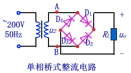
1. Single-Phase Bridge Rectifier Circuit
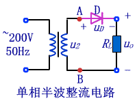
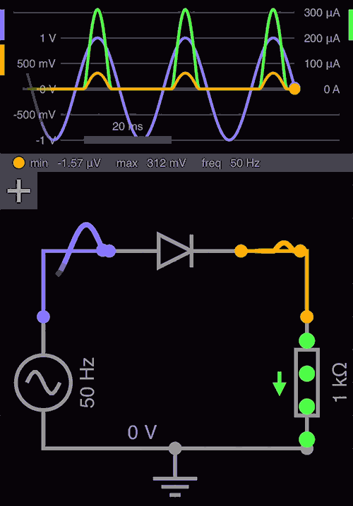
2. Single-Phase Half-Wave Rectifier Circuit
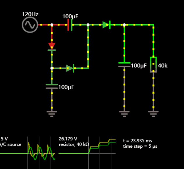
3. Full-Wave Rectifier Circuit
4. Comparison of Full-Wave and Half-Wave Rectification
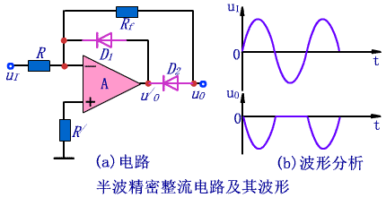
5. Half-Wave Precision Rectifier Circuit
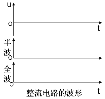
6. Half-Wave Rectification Waveform Analysis
A half-wave rectification is achieved using a single diode. The 1kΩ resistor serves as the load. The half-wave rectifier circuit converts “AC voltage” into “pulsating DC voltage”. The term “pulsating DC voltage” refers to a voltage whose direction (positive and negative) remains constant, but its magnitude varies over time. The waveforms at various points are as follows:
Full Article: Intuitive Experience of Circuit Signal Waveforms: Half-Wave Rectifier Circuit
7. Boost Circuit
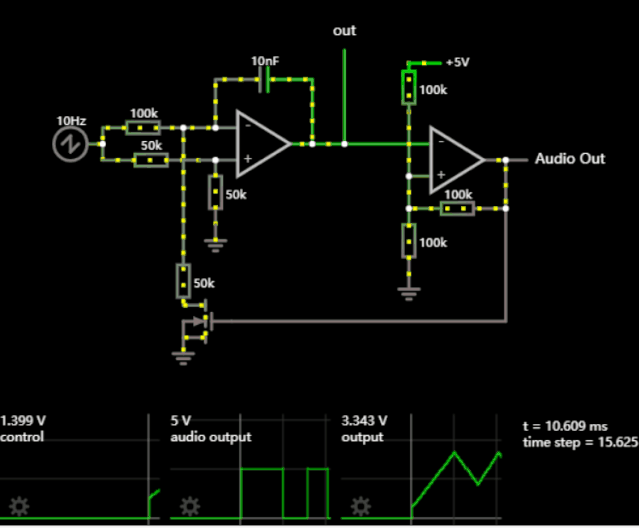
8. Voltage-Controlled Oscillator
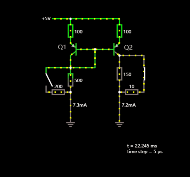
9. Current Mirror
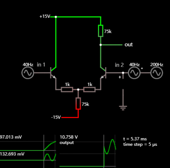
10. Differential Amplifier
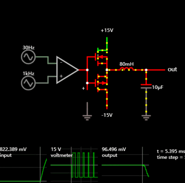
11. Class D Amplifier
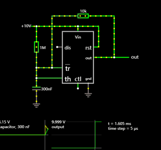
12. 555 Square Wave Oscillator
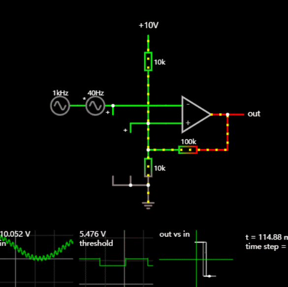
13. Schmitt Trigger
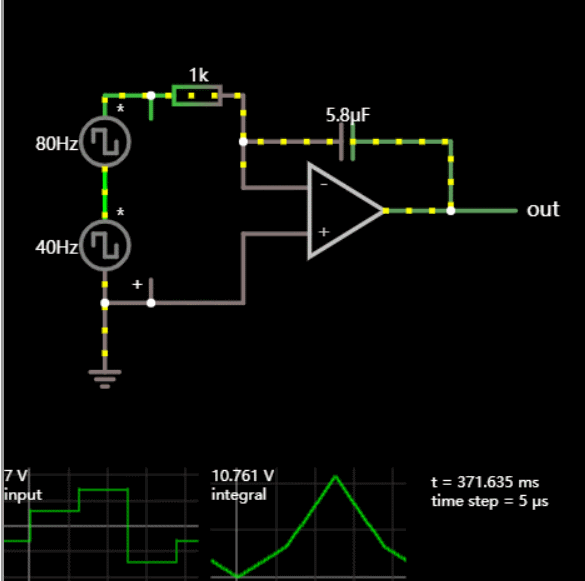
14. Integrator
15. Differentiator

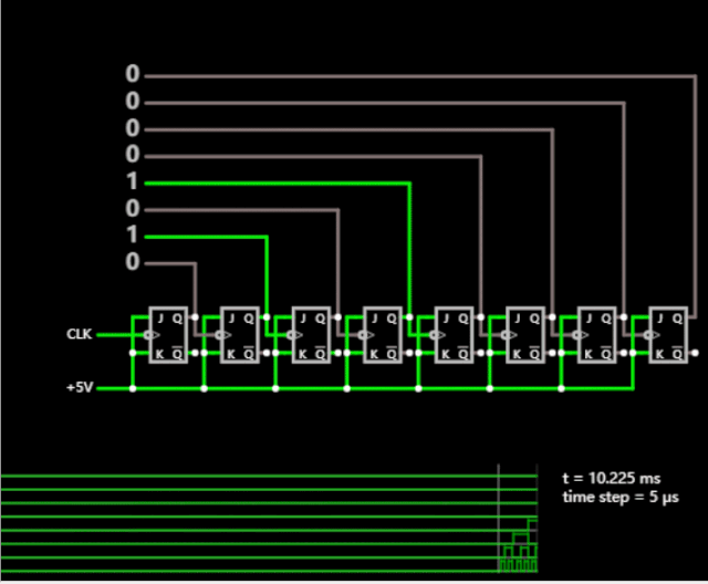
16. 8-Bit Asynchronous Counter
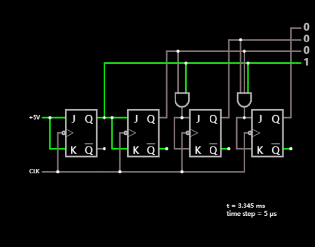
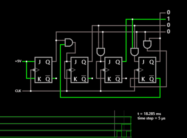
17. 4-Bit Synchronous Counter
18. 4-Bit Decimal Counter
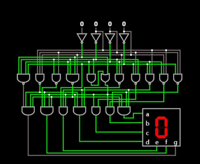
19. 7-Segment LED Decoder
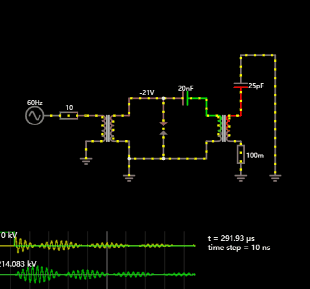
20. Tesla Coil
It’s okay if some diagrams are hard to understand; experiencing them is still rewarding.
Just like in college, many people may feel lost, but after four years, there will always be some change.

Sharing a lightweight C language library for Modbus
MCU Fan Hardware and Software Algorithm Solutions
Analyzing MCU Stack Space through Case Studies