Click the blue text above to follow us
01. Internal Data Transfer Instructions of the Processor
>>>
The most common operation performed by the processor is transferring data back and forth within the processor. Common operations include:
①. Transferring data from one register to another.
②. Transferring data from a register to special registers like CPSR and SPSR.
③. Transferring an immediate value to a register.
Three commonly used instructions for data transfer are:MOV、MRS and MSR, as shown in the table below:
1. MOV Instruction
The MOV instruction is used to copy data from one register to another or to transfer an immediate value into a register. Examples are as follows:
MOV R0,R1 @This transfers the data in register R1 to R0, i.e., R0=R1
MOV R0, #0X12 @This transfers the immediate value 0X12 to register R0 , i.e., R0=0X12
2. MRS Instruction
The MRS instruction is used to transfer data from special registers (like CPSR and SPSR) to general-purpose registers. To read data from special registers, only the MRS instruction can be used! The example is as follows:
MRS R0, CPSR @This transfers the data from the special register CPSR to R0, i.e., R0=CPSR
3. MSR Instruction
The MSR instruction is the opposite of MRS; it is used to transfer data from general-purpose registers to special registers, i.e., writing to special registers can only be done using MSR. The example is as follows:
MSR CPSR, R0 @This copies the data in R0 into CPSR, i.e., CPSR=R0

02. Memory Access Instructions
>>>
ARM cannot directly access memory, such as data in RAM. The registers in I.MX6UL are of RAM type. When configuring I.MX6UL registers using assembly, we need to rely on memory access instructions. Generally, we first write the value to be configured into the Rx (x=0~12) registers and then use memory access instructions to write the data in Rx to the I.MX6UL registers. Reading the I.MX6UL registers follows the same process, just in reverse. The two commonly used memory access instructions are:LDR andSTR.
1. LDR Instruction
LDR is mainly used to load data from memory into register Rx. LDR can also load an immediate value into register Rx, but when loading an immediate value, it must use “=” instead of “#”. In embedded development, LDR is most commonly used to read the value of the CPU’s registers. For example, in I.MX6UL, there is a register GPIO1_GDIR with the address 0X0209C004. To read the data from this register, the example code is as follows:
1 LDR R0, =0X0209C004 @This loads the register address 0X0209C004 into R0 , i.e., R0=0X0209C004
2 LDR R1, [R0] @Reads the data from address 0X0209C004 into register R1
The above code reads the value from the GPIO1_GDIR register, and the read value is stored in register R1. The offset in the above code is 0, meaning no offset is used.
2. STR Instruction
LDR reads data from memory, while STR writes data into memory. Using the I.MX6UL register GPIO1_GDIR as an example, if we want to set the value of the GPIO1_GDIR register to 0X20000002, the example code is as follows:
1 LDR R0, =0X0209C004 @This loads the register address 0X0209C004 into R0 , i.e., R0=0X0209C004
2 LDR R1, =0X20000002 @R1 stores the value to be written to the register, i.e., R1=0X20000002
3 STR R1, [R0] @This writes the value in R1 to the address stored in R0
LDR and STR read and write data by word, which means operating on 32-bit data. If you want to operate by byte or half-word, you can add B or H after the instruction “LDR”, such as LDRB and STRB for byte operations, and LDRH and STRH for half-word operations.

03. Push and Pop Instructions
>>>
We often call function B from function A. After function B completes execution, it returns to continue executing function A. To ensure that the code can continue to run normally after returning to function A, we must save the current processor state (i.e., save the values of registers R0~R15) before jumping to function B. After function B completes execution, we restore R0~R15 using the previously saved register values. The operation of saving R0~R15 is called context saving, and restoring R0~R15 is called context restoring. During context saving, a push operation is performed, and during context restoring, a pop operation is performed. The push instruction is PUSH, and the pop instruction is POP. Both PUSH and POP can operate on multiple registers at once, utilizing the current stack pointer SP to generate addresses. The usage of PUSH and POP is as follows:
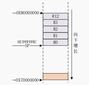
If we want to push registers R0~R3 and R12, with the current SP pointer pointing to 0X80000000, and the processor stack growing downwards, the assembly code is as follows:
PUSH {R0~R3, R12} @This pushes R0~R3 and R12 onto the stack
This is the stack diagram after pushing R0~R3 and R12. At this point, the SP points to 0X7FFFFFEC.
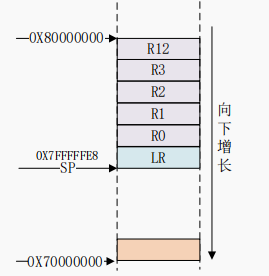
If we now want to push LR, the assembly code is as follows:
PUSH {LR} @This pushes LR onto the stack
The above two steps push R0~R3, R12 and LR onto the stack. If we want to pop, we use the following code:
POP {LR} @First restore LR
POP {R0~R3,R12} @Then restore R0~R3,R12
Popping is done from the top of the stack, starting from the current execution position of SP, with addresses decreasing sequentially to extract data from the stack into the registers to be restored. Another way to write PUSH and POP is “STMFD SP!” and “LDMFD SP!”, therefore the above assembly code can be changed to:
1 STMFD SP!,{R0~R3, R12} @R0~R3,R12 push
2 STMFD SP!,{LR} @LR push
3
4 LDMFD SP!, {LR} @First restore LR
5 LDMFD SP!, {R0~R3, R12} @Then restore R0~R3, R12
STMFD can be divided into two parts: STM and FD, similarly, LDMFD can also be divided into LDM and FD. Upon seeing STM and LDM, do you feel a sense of déjà vu (not STM32, ah)? Previously, we discussed LDR and STR, which are data load and store instructions, but can only read or write one piece of data in memory at a time. STM and LDM can perform multiple stores and loads, allowing for continuous reading and writing of multiple consecutive data in memory.
FD is an abbreviation for Full Descending, meaning fully descending. According to ATPCS rules, ARM uses FD type stacks, where SP points to the last value pushed onto the stack, and the stack grows downwards from high address to low address, as mentioned earlier.

04. Jump Instructions
>>>
①. Directly use jump instructions B、BL、BX etc.
②. Directly write data into the PC register.
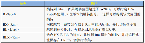
We will focus on the B and BL instructions, as these are the most commonly used. To perform function calls in assembly, we use the B and BL instructions:
1. B Instruction
This is the simplest jump instruction. The B instruction sets the value of the PC register to the target jump address. Once the B instruction is executed, the ARM processor immediately jumps to the specified target address. If the function to be called will not return to the original execution point, then the B instruction can be used, as shown in the example:
1 _start:
2
3 ldr sp,=0X80200000@Set stack pointer
4 b main @Jump to main function
2. BL Instruction
Compared to the B instruction, the BL instruction saves the current value of the PC register in the LR (R14) register before jumping, allowing us to continue from the code point before the jump by reloading the value from the LR register into the PC. This is a fundamental but commonly used means of subroutine calls. For example, the irq interrupt service functions of the Cortex-A processor are written in assembly, mainly to implement context saving and restoring, obtaining interrupt numbers, etc. However, the specific interrupt handling process is done in C functions, which can lead to issues when calling C functions from assembly. Additionally, when the C language version of the interrupt handler completes execution, it needs to return to the irq assembly interrupt service function to handle other tasks, usually restoring the context. At this point, we cannot use the B instruction directly, as once the B instruction jumps, it will not return. Instead, we need to use the BL instruction, as shown in the example code:
1 push {r0, r1}@Save r0,r1
2 cps #0x13@Enter SVC mode, allowing other interrupts to enter again
3
5 bl system_irqhandler @Load C language interrupt handler into r2 register
6 cps #0x12@Enter IRQ mode
8 pop {r0, r1}@Restore r0,r1
9 str r0, [r1, #0X10] @Interrupt execution completed, write EOIR
In the above code, line 5 executes the C language version of the interrupt handler. After processing is complete, it needs to return to continue executing the following program, so the BL instruction is used.
05. Arithmetic Operation Instructions
>>>
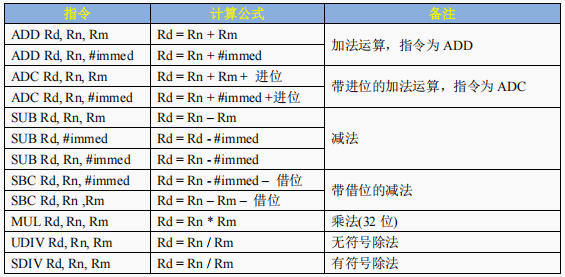
Arithmetic operations can also be performed in assembly, such as addition, subtraction, multiplication, and division.
In embedded development, the most commonly used instructions are addition and subtraction, while multiplication and division are rarely used.
Learning Communication and Part-time Recommendations

06. Logic Operation Instructions
>>>

Summary
>>>
Protecting eyesight methods

So I Am Here
Click the card below to follow me
↓↓↓

If you like it, please click
Collect
Like
Looking
+1