With the development of the automotive industry, the number of electronic control systems in vehicles has grown exponentially. The in-vehicle electronic control system, centered around the ECU, is gradually replacing passive devices and mechanical systems, while also fulfilling most measurement, drive, and control functions. The increase in new in-vehicle electronic control systems in vehicle applications has led to an annual increase in power load of approximately 100W. The biggest challenge currently faced is finding new methods to ensure the continuous increase in the number and functionality of automotive electronic devices under the same battery power conditions. Therefore, it is necessary to continuously reduce the power consumption of the MCU in practical applications.
Automotive Power Electronic Circuit Diagram
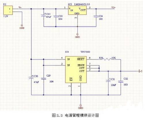
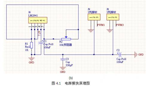
LM2940: 5V, voltage drop 0.5V. The 2940 series linear voltage regulator chip was chosen for its low ripple and simple circuit structure, used to power microcontrollers, laser sensors, and encoders; LM1117-ADJ: 6V voltage for servos; LM1117-3.3: 3.3V voltage for wireless modules.
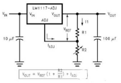
LM2940: 5V, LM1117-ADJ: 6V voltage for servos.
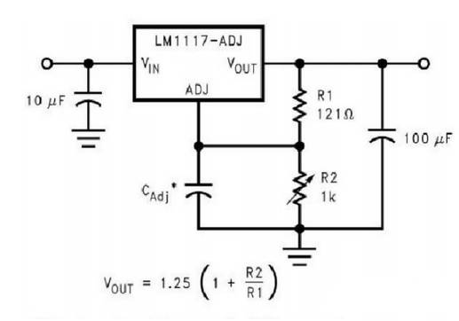
The standard car model used for the intelligent car competition is powered by a 7.2V 2000mAh Ni-Cd battery, while the microcontroller, laser sensors, and photoelectric encoders all require a 5V power supply. The rated working voltage for the servo motors (including the front wheel steering servo and rear wheel braking servo) is 6V, and the DC motor can be powered directly by the 7.2V battery. The 5V voltage regulator is used to power the microcontroller, laser sensor module, and photoelectric encoder module.
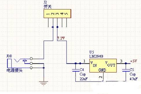
Experimental results show that the 5V voltage regulation circuit built using LM2940 can stably power these modules, ensuring functionality without mutual interference, and the entire circuit is simple and practical. The servo voltage regulator is provided by a voltage regulation circuit composed of LM2941, with adjustable output voltage (by adjusting the 10k potentiometer in the diagram).
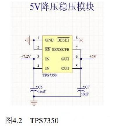
Since the +5V circuit in the entire system has relatively low power consumption, a linear voltage regulation circuit is considered to reduce power supply ripple. Additionally, when the rear-wheel drive motor operates, the voltage drop across the battery is significant; to improve system stability, a low-dropout voltage regulator chip must be used. Common low-dropout linear voltage regulator chips include 2940, 1117, etc. Although 2940 has a lower voltage drop than 1117, it has a higher ripple voltage. In contrast, 1117 exhibits better performance, maintaining a constant output voltage with a lower voltage drop; however, its linear adjustment working method can lead to significant thermal losses during operation, resulting in low power utilization and efficiency. The TPS7350 is a low-power low-dropout linear power supply chip with comprehensive protection circuits, including overcurrent, overvoltage, and reverse voltage protection. Using this chip requires very few external components to form an efficient voltage regulation circuit. Compared to the previous two voltage regulators, the TPS7350 has a lower operating voltage drop and smaller static operating current, allowing for relatively longer battery life. Due to its low thermal loss, special consideration for heat dissipation is unnecessary.
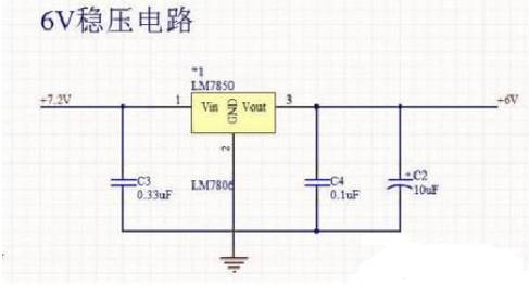
LM7806 is a 6V voltage regulator chip, specifically selected for the servos in this car model. Previously, the servos in model A were generally powered by the supply voltage, but due to the susceptibility of model B’s servos to damage, the supply voltage must be reduced, hence the selection of the LM7806 as the 6V voltage regulator chip.
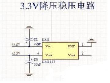
LM1117-3.3V is a 3.3V voltage regulator chip. The LM1117 has two models, namely 5V and 3.3V voltage regulators; the 3.3V voltage regulator chip is mainly used to power the acceleration sensor MMA7260.
The circuit system is the core of the intelligent vehicle hardware system; for this hardware circuit system, stability is the primary performance indicator to ensure, as completing the entire course is the prerequisite for achieving results. Based on this, other indicators such as the dynamics, center of gravity, and compactness of the circuit board should also be considered comprehensively.
Motor Drive Module
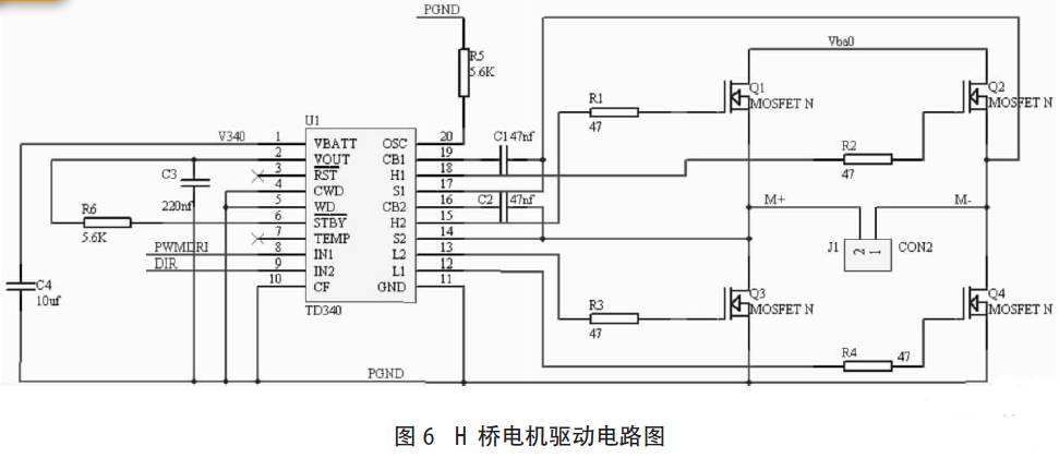
The motor drive module provides power for the movement of the intelligent vehicle, and its performance directly affects the control performance of the rear-wheel motor, including acceleration, deceleration, and braking. This article adopts a MOSFET driving chip with a full-bridge driving scheme, only requiring a reasonable selection of the MOSFET driving chip and power MOSFET to ensure performance. The circuit diagram is shown in Figure 6.
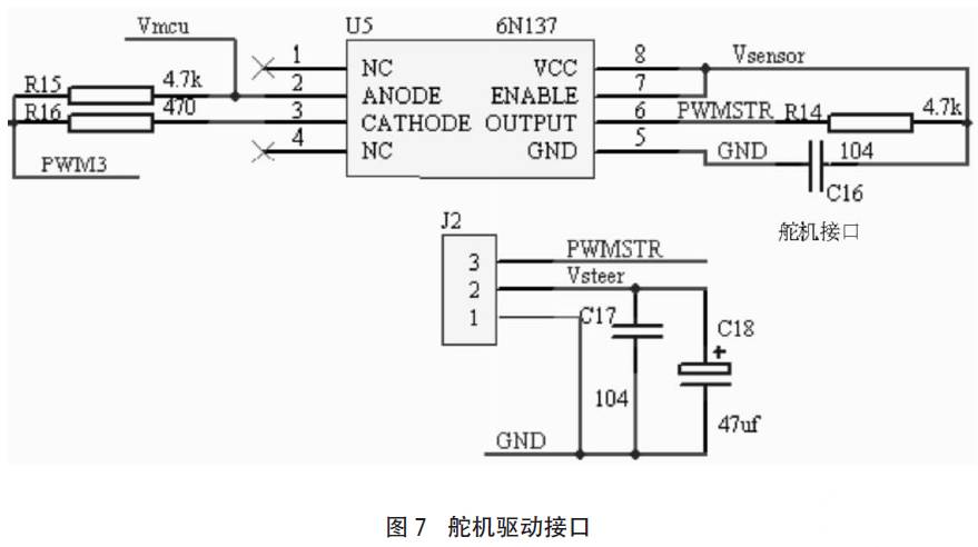
Servo Drive Module
The servo is responsible for the steering of the intelligent vehicle, and the stability of the servo module directly affects the stability of the intelligent vehicle when driving at high speeds on the track, as well as the sensitivity and accuracy during steering. The working principle of the servo is determined by the pulse width of the PWM control signal emitted by the microcontroller, which adjusts the servo angle through feedback control within the internal circuit. Since the servo itself is an angle closed-loop control with good performance, there is no need to consider an external servo closed-loop in the system. The circuit for the servo drive module is shown in Figure 7. The servo drive module is also part of the power section and uses a 6N137 optocoupler for signal isolation.
Intelligent vehicles are a complex integrated system involving multiple fields. To achieve practical purposes, further in-depth research is needed, and there is still much work to be done. On the hardware side, issues such as differences in camera precision or data loss due to external factors affecting the normal operation of the intelligent vehicle need to be resolved to enhance anti-interference capabilities; on the software side, algorithms need further optimization. The control system is the core content of the intelligent vehicle; based on the functional requirements of the intelligent vehicle, key modules of the intelligent vehicle control system have been studied, and the designed modules have been applied in the “Freescale” intelligent vehicle, with the images in the article providing inspiration for the research of intelligent vehicles.
Interpreting the NCV70522 ($2.8420) Automotive Adaptive Headlight System Circuit
Typically, the motor’s back electromotive force (BEMF) can be used to determine whether the motor is stalled. BEMF varies with motor speed, load, and supply voltage. Traditional stepper motor driver chips do not have BEMF output but include built-in stall detection algorithms. Customers can only set a fixed stall detection threshold in the register, meaning all settings must be “offline” preset before working under real road conditions and cannot adapt to actual working conditions. The NCV70522 micro-stepping stepper motor driver provides BEMF output through the SLA pin, allowing for real-time stall detection calculations and adjusting detection levels based on different conditions.
Algorithm Application
The NCV70522 is a micro-stepping stepper motor driver used for bipolar stepper motors. This chip connects to an external microcontroller via I/O pins and SPI interface. The NCV70522 offers multiple output current options. It rotates to the next micro-step based on the pulse signal on the “NXT” input pin and the state of the direction register [DIRCTRL] or “DIR” input pin. The device provides seven stepping modes from full-step to 32 micro-steps, selectable via the SPI register SM[2:0]. The NCV70522 includes SLA output, which can be used for stall detection algorithms and to adjust torque and speed calculations based on the motor’s BEMF. A typical application circuit diagram is shown.
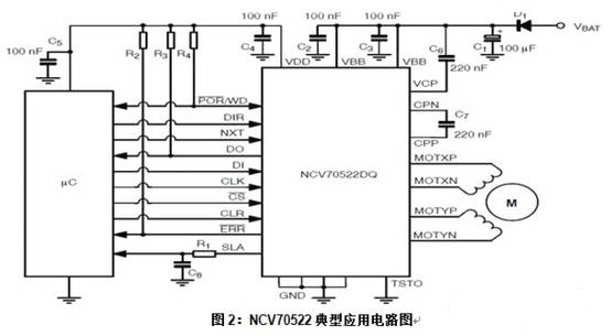
When the system is powered on, the microcontroller initializes, and the NCV70522 resets. Once these actions are completed, the coil current and stepping mode will be set. The motor driver will then be enabled. NXT pulses will be sent to rotate the motor. The motor speed equals the NXT pulse frequency multiplied by the stepping subdivision mode value.
An Embedded Automotive Digital Instrument Circuit Design
Power Supply and Reset Circuit Design
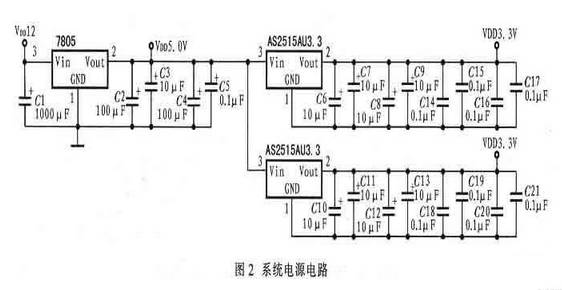
The automotive digital instrument system is powered by the automotive battery, which has a voltage of approximately 12V. However, the system requires operating voltages of 5V, 2.5V, and 3.3V. The S3C44BOX core operates at 2.5V, the I/O ports operate at 3.3V, and the conditioning circuits and some driving devices require a 5V operating voltage. Therefore, the system selects the 7805 voltage regulator as the 5V voltage converter and uses AS2515AU2.5 and AS2515AU3.3 as the 2.5V and 3.3V voltage converters, respectively. During power-off, a 1000μF capacitor must be connected to the power ground to promptly store mileage information. During power-off, the large capacitor can ensure that the S3C44BOX operates for a period of time to complete the storage of mileage information. The reset circuit uses a dedicated reset circuit IPM811 to achieve stable system startup. Figure 2 shows the system power circuit.
Speed, Water Temperature, Oil Level, and Switch Signal Processing Circuit Design
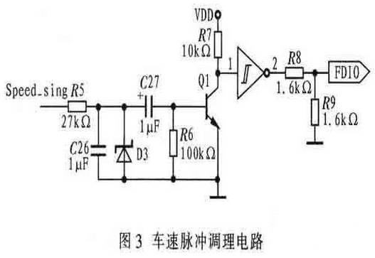
Since automobiles mostly operate in harsh environments, they can interfere with speed sensor signals. Therefore, the speed pulse signal must be conditioned before inputting it to the interrupt port EINT0. Here, RC filtering, transistor amplification, and Schmitt shaping methods are used to condition the speed pulse signal. The speed pulse conditioning circuit is shown in Figure 3.
The water temperature and oil level signals are resistance signals that must be converted into voltage signals before being input to the AD port of the S3C44BOX. Other switch signals are filtered and reduced before being input to the I/O port of the S3C44BOX.
CAN Bus Communication Circuit Design
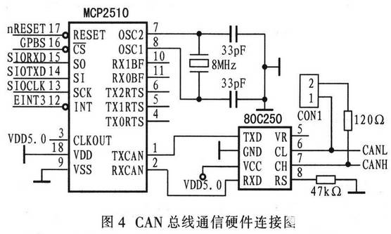
The S3C44BOX does not have an SPI interface but has an SIO interface. The SIO module can latch data bits on both the rising and falling edges; therefore, by setting the registers corresponding to the SIO module of the S3C44BOX, data can be sent on the rising edge and received on the falling edge, aligning with the SPI bus timing of the MCP2510. The CAN bus communication circuit is shown in Figure 4.
Stepper motor gauge circuit, etc. The stepper motor uses Switec’s automotive gauge dedicated stepper motor X15.168, along with a dedicated four-channel stepper motor driver device X12.017. The I/O level of the S3C44BOX is 3.3LVCMOS level, while X12.017 is 5VCMOS level, requiring the use of a 74LVX4245 level converter.
Using the S3C44BOX and the embedded real-time operating system μC/OS_II, a high-precision, high-sensitivity, and stable working embedded bus automotive digital instrument has been designed. The S3C44BOX is resource-rich and fast in execution, capable of expanding many functions such as IC cards, GPS, black boxes, etc.; coupled with the embedded real-time operating system simplifying application programs, it can efficiently and real-time invoke system tasks. Therefore, this automotive digital instrument system can effectively solve the problem of automotive instruments moving towards comprehensive informationization.
Note: Automotive electronics are considered a revolution in the development of automotive technology, enhancing the safety, comfort, economy, and entertainment of vehicles. They can currently be divided into two major categories: first, automotive electronic control devices, including powertrain control, chassis and body electronic control, comfort and anti-theft systems; second, in-vehicle automotive electronic devices, including automotive information systems, tire pressure monitoring systems, navigation systems, etc.