

The previous issue mainly introduced the eutectic adhesive method. This article discusses the solder paste method in chip mounting, exploring the technology that utilizes alloy reactions to achieve chip adhesion. The solder paste method, with its excellent thermal conductivity, has become a commonly used mounting method for high-power components.

If you want to stay updated, click above to follow and set as a star!
1. Core Principle of the Solder Paste Method
The essence of the solder paste method is to form a reliable mechanical connection and electrical pathway between the chip and the substrate through the melting and solidification of alloy materials. Its core principle is similar to that of the eutectic adhesive method, both relying on intermetallic alloy reactions, but there are significant differences in material selection and process details.
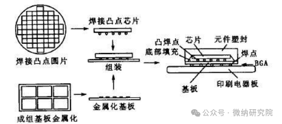
From a process flow perspective, the steps of the solder paste method are quite systematic. First, the chip and pads must undergo metallization: a certain thickness of Au or Ni is deposited on the back of the chip. This metal layer not only enhances the wettability of the chip with the solder but also prevents corrosion of the chip body by the solder; simultaneously, a composite metal layer of Au-Pd-Ag and Cu is deposited on the pads, which improves the oxidation resistance and mechanical strength of the pads, laying the foundation for subsequent soldering.
The next step is the critical soldering phase. The solder made from Pb-Sn alloy, when melted at a specific temperature, will undergo a diffusion reaction with the metal layers on the back of the chip and the pads, solidifying upon cooling to form a strong bond. The soldering temperature is not arbitrarily set; it entirely depends on the specific composition of the Pb-Sn alloy—for example, the common 63% Sn-37% Pb eutectic alloy has a melting point of only 183°C, while high-lead solders have significantly higher melting points.
It is important to note that the entire process must be conducted in a hot nitrogen or other inert gas environment. This is because solder is highly prone to oxidation at high temperatures, and the resulting oxide layer can hinder the wettability and diffusion of the solder, leading to voids at the bonding interface. Research data shows that when the void rate caused by oxidation exceeds 5%, thermal conductivity efficiency can drop by more than 30%, severely affecting device reliability.
2. The “Soft vs. Hard” Debate of Solder Materials
The flexibility of the solder paste method is largely reflected in the choice of solder materials. In the industry, solders are typically divided into hard and soft solders, and their characteristic differences directly determine their applicable scenarios.
Hard solders, represented by gold-silicon, gold-tin, and gold-germanium alloys, have high plastic deformation stress values and excellent fatigue and creep resistance. For example, gold-tin eutectic solder (80% Au-20% Sn) has a melting point of 280°C and can maintain a shear strength of over 50MPa at high temperatures of 150°C, making it very suitable for devices that operate in high-temperature environments. However, the downside is that hard solders are rigid and struggle to mitigate stress damage caused by differences in the coefficient of thermal expansion (CTE) between the chip and substrate. When the CTE mismatch exceeds 5ppm/°C, cracks are likely to occur at the bonding interface of hard solders during thermal cycling tests.
Soft solders, on the other hand, are typified by lead-tin and lead-silver-indium alloys, with their greatest advantage being good plasticity, allowing them to absorb thermal stress through their own deformation. For instance, 60% Pb-40% Sn solder has stress relief capabilities that are more than three times that of gold-tin solder during temperature cycling from -55°C to 125°C. However, soft solders also have a “soft spot”—they must first have multiple layers of metal films (usually Cr/Cu/Au or Ti/Ni/Au structures) deposited on the back of the IC chip to ensure good wettability of the solder. This metal film acts as an “intermediary,” forming a strong bond with the chip and undergoing an alloy reaction with the solder, both of which are essential.
3. Similarities and Differences with the Eutectic Adhesive Method: Which is Superior?
Since both the solder paste method and the eutectic adhesive method utilize alloy reactions, what are their core differences? Let’s make a comparison.
From a commonality perspective, both rely on intermetallic diffusion reactions to form bonds, and the medium is metal materials, thus both possess good thermal conductivity properties, which is the core reason they can be used for high-power device packaging. Test data shows that the thermal resistance of high-quality solder joints can be as low as 0.5°C/W, on par with eutectic joints.
However, the differences are more critical. The eutectic adhesive method primarily relies on gold-silicon eutectic reactions, with a relatively simple material system; whereas the solder paste method has a wider range of solder selection, allowing for adjustments in composition to adapt to different temperature requirements and stress environments. Additionally, the process temperature of the eutectic adhesive method is typically around 425°C, while the solder paste method can control the temperature between 180-300°C depending on the solder composition, resulting in less thermal damage to the chip.
However, the solder paste method also has its drawbacks: the lead in Pb-Sn solder is a toxic substance, and with the tightening of environmental regulations such as RoHS, lead-free solutions have become an inevitable trend. Currently, the industry has developed lead-free solders such as Sn-Ag-Cu (SAC), but these solders have higher melting points (around 217°C) and poorer wettability compared to traditional Pb-Sn solders, requiring optimization of process parameters to compensate.
4. Why is the Solder Paste Method Mainly Used for High-Power Component Packaging?
The “main battlefield” of the solder paste method is in the packaging of high-power components, such as power diodes and IGBTs (Insulated Gate Bipolar Transistors). This is because these devices generate a lot of heat during operation, and the high thermal conductivity of the solder joint ensures rapid heat dissipation, preventing excessive junction temperatures that could lead to performance degradation. In the motor controllers of electric vehicles, IGBT modules soldered with Pb-Sn solder can achieve thermal cycling lifetimes of over 1000 cycles, meeting automotive-grade reliability requirements.

Like + ViewShare with your friends! ↓