Overview of CAN
CAN is an abbreviation for Controller Area Network (hereinafter referred to as CAN).
CAN belongs to the category of field buses, and it is a serial communication network that effectively supports distributed control or real-time control, known as the computer local area network in the field of automation.
The CAN bus is a serial data communication protocol developed by the German company BOSCH in the early 1980s to solve data exchange between numerous control and testing instruments in modern automobiles.
Application Scenarios of CAN Bus
The CAN bus is suitable for use in fields with high real-time requirements, multi-master and multi-slave configurations, or equal nodes, such as communication between modular large instrument systems, constructed using a modular networking approach.
Example of Siemens CT CAN Communication
CAN bus diagram in Siemens SOMATOM Definition:
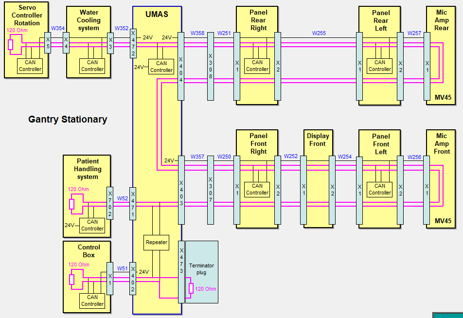
In this device’s CAN bus, there are 9 CAN nodes communicating on a single bus.
The 9 nodes are: one Control Box at the operating station, one UMAS at the stationary part of the rack, four control panels for the front and back covers, one for bed control, one for water cooling, and one for rack rotation.
Any node among the 9 can directly conduct efficient data communication.
Model Simplification
Although different nodes perform different functions, they all have the same hardware and software structure.
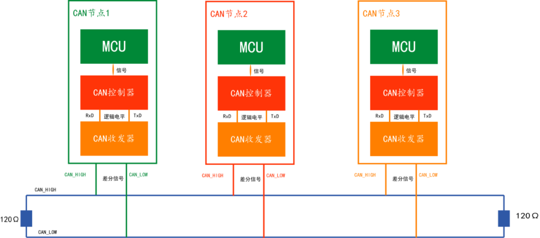
The bus structure is modeled, and the simplified model is as follows:
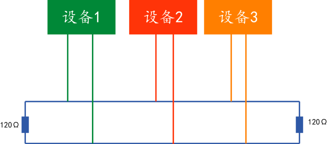
This model is the CAN high-speed topology.
Why is it 120Ω? Because the characteristic impedance of the cable is 120Ω, in order to simulate an infinitely long transmission line.
Basic Principles
When a node (station) on the CAN bus sends data, it broadcasts it to all nodes in the network in the form of messages. For each node, regardless of whether the data is addressed to itself, it will receive it.
When a station wants to send data to other stations, the station’s CPU transmits the data to be sent along with its identifier to the CAN chip of this station and is in preparation mode; when it receives bus allocation, it switches to message sending mode.
The CAN chip organizes the data into a specific message format according to the protocol, and at this time, other stations on the network are in receiving mode.
Each station in receiving mode checks the received messages to determine whether they are addressed to itself to decide whether to accept them.
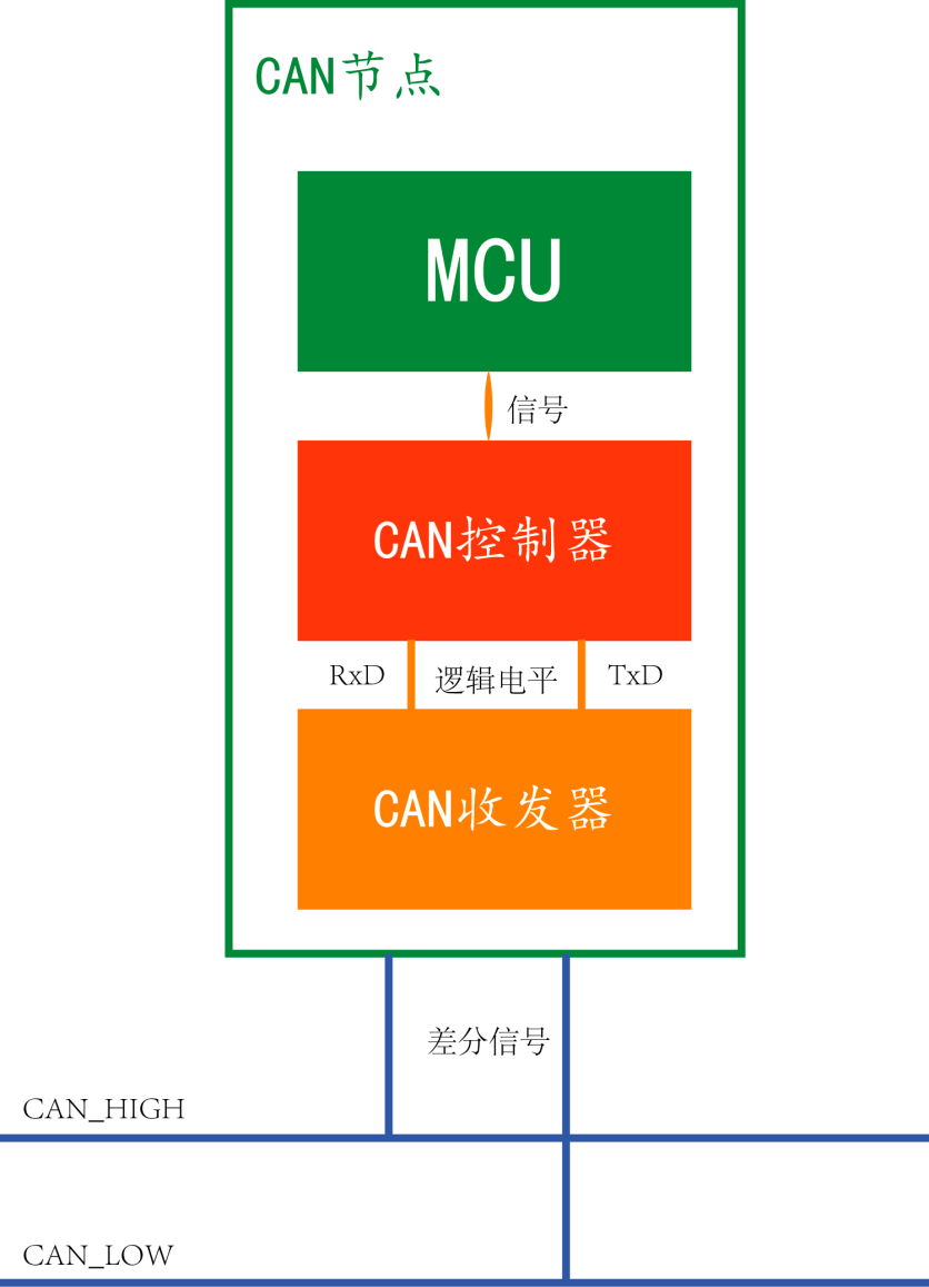
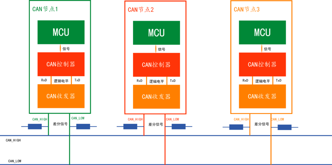
CAN Node Model
Each CAN node has the same hardware and software structure, and CAN nodes are typically divided into three parts: MCU/CPU, CAN controller, and CAN transceiver.
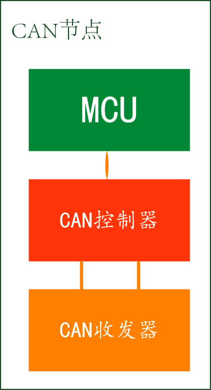
The CAN controller is used to convert the messages (frames) to be transmitted into CAN frames that comply with CAN specifications, and exchanges information over the CAN bus through the CAN transceiver; during the transmitting and receiving process, it performs bit stuffing, adds CRC checks, acknowledgment checks, and other operations; it also needs to handle conflict detection, error handling, and many other tasks.
The CAN transceiver is the interface between the CAN controller and the physical bus, converting the logic levels of the CAN controller into differential levels on the CAN bus, transmitting data over two cables with differential voltage.
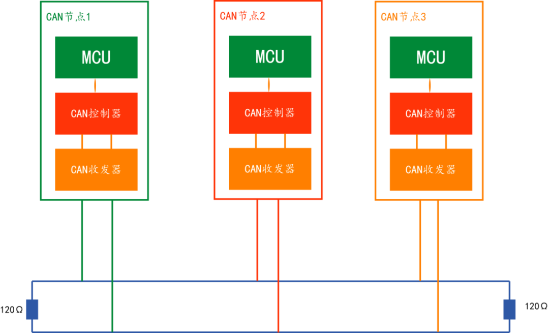
The CAN model is further refined as follows:
Signal Flow of CAN Nodes
The overall process is as follows:
1. Data transmission on the CAN bus occurs through differential signals;
2. The CAN transceiver converts the differential signals into logic level signals or vice versa;
3. The CAN controller receives the TTL level signals and transmits them to the MCU;
Based on the signal flow, the CAN high-speed communication model is refined as follows:
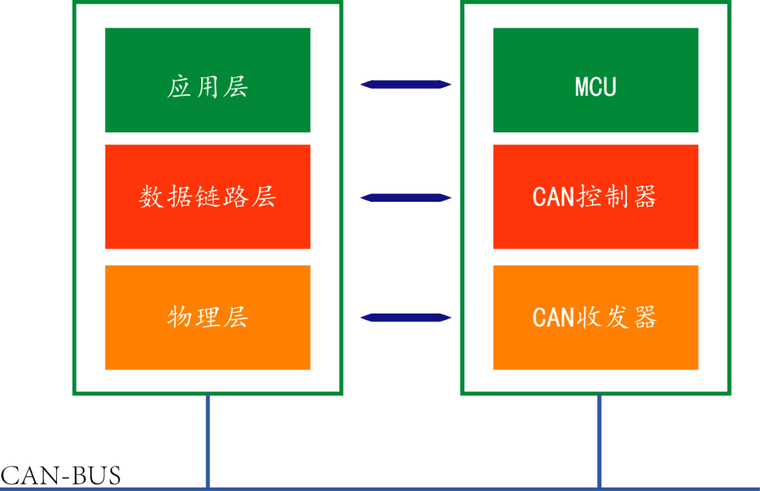
CAN Protocol Model
The protocol modeling of nodes in CAN communication is as follows:
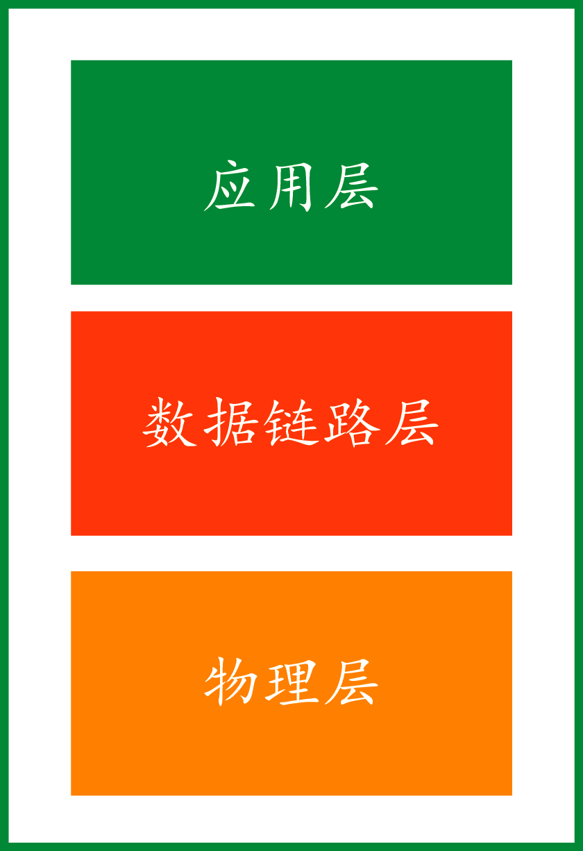
Physical Layer
The physical layer is the hardware topology structure mentioned earlier, including high-speed CAN and low-speed CAN, while the CAN transceiver belongs to the physical layer;
Data Link Layer
The data link layer is the responsibility of the CAN controller, including CAN timing, synchronization, message arbitration, acknowledgment, error checking, etc.;
Application Layer
The application layer is a further encapsulation based on the object layer, including different CAN standards, such as CANopen in the field of industrial automation and UDS defined by automotive diagnostics ISO 14229, etc.;
CAN Bus Arbitration
The CAN bus does not use a master-slave control method like RS485; it is a multi-master bus, where all connected nodes are independent. So, when many nodes want to send and receive data simultaneously, will it cause a communication breakdown on the bus?
This issue was also considered by the developers of the CAN line, so they decided to define priorities in the content being sent, allowing the Frame ID to include priority information, specifying that when two or more data messages are sent and received simultaneously on the CAN bus, the bus will determine based on the node ID of the data sender; the node with the smaller frame ID has a higher priority, allowing multiple data to be transmitted sequentially, which is the CAN data arbitration.
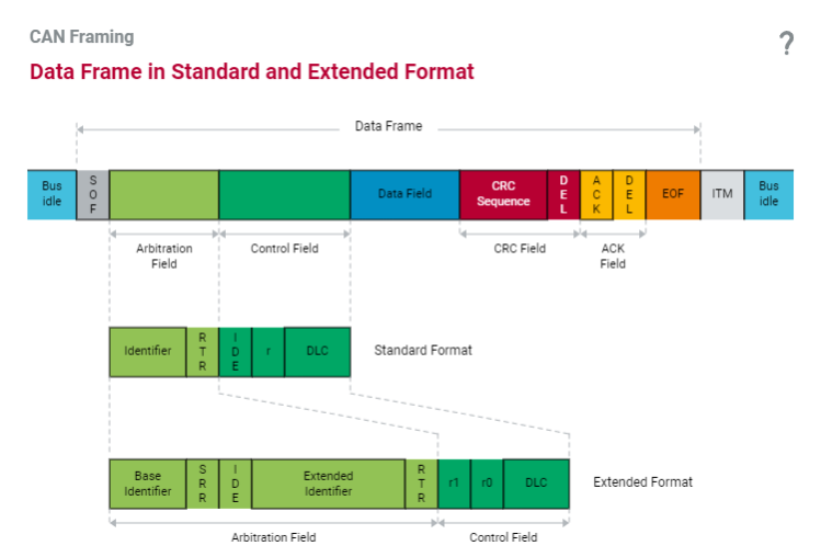
Message
The CAN bus transmits data in units of messages, and messages consist of seven different bit fields, structured as follows:
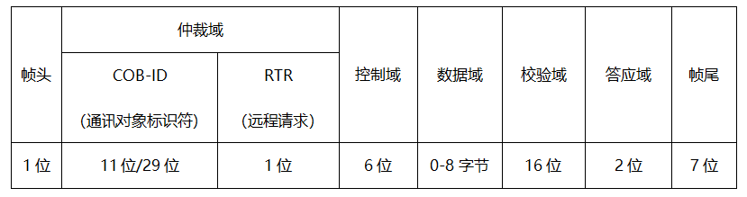
Among them, the COB-ID contains priority information.
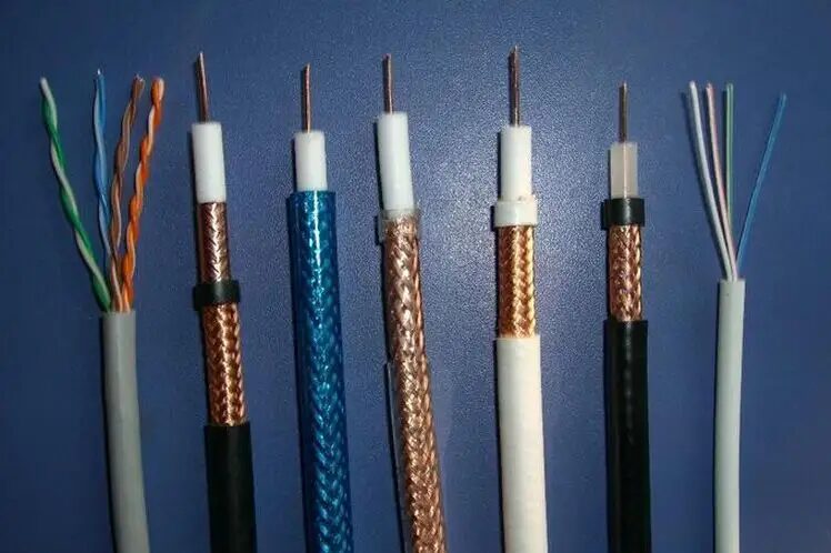
Communication Medium
The communication medium can be twisted pair, coaxial cable, or optical fiber.
Transmission Speed and Distance
The communication rate can reach up to 1Mbps.
The maximum communication distance can reach 10KM (with a rate below 5Kbps) and can reach 1Mbps (communication distance less than 40M);
According to the transmission speed, the CAN system is divided into high-speed and low-speed, with different requirements using different speeds and topologies.
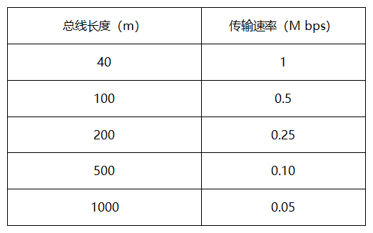
Among them, the commonly used communication rate in general engineering is 500Kbps for high-speed communication.
ISO Certification
CAN has been standardized through ISO11898 and ISO11519, making it a serial communication protocol standardized by ISO.
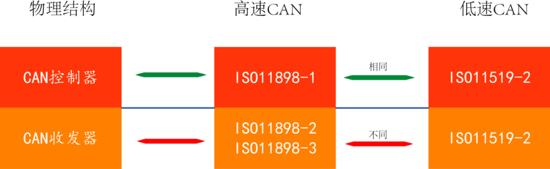
Low-Speed CAN Topology
The high-speed CAN topology and low-speed topology differ, with the high-speed topology introduced earlier; the following is the low-speed topology diagram:
What is CANopen
CAN provides all network management services and message transmission protocols, but does not define the content of the objects or the types of objects being communicated (it only defines how, not what), which is the entry point for CANopen.
CANopen is a higher-level communication protocol built on CAN, including communication sub-protocols and device sub-protocols, commonly used in embedded systems and a frequently used field bus in industrial control.
Characteristics of CAN Bus
The CAN bus is designed for the measurement and control field, requiring rapid data transmission for real-time processing, which necessitates a high-speed physical transmission path. When several stations need to send data simultaneously, rapid bus allocation is required.
Several characteristics include:
1. Simple structure: The bus has only two communication lines;
2. Anti-interference: The physical layer uses differential signals, which have strong anti-interference capabilities;
3. High speed: Necessary for processing real-time data;
4. Freedom to add or remove nodes within the network;
5. Any nodes on the bus can communicate freely with each other;
6. The amount of data transmitted in a single message is small, with a maximum data limit of 8 bytes per message;