
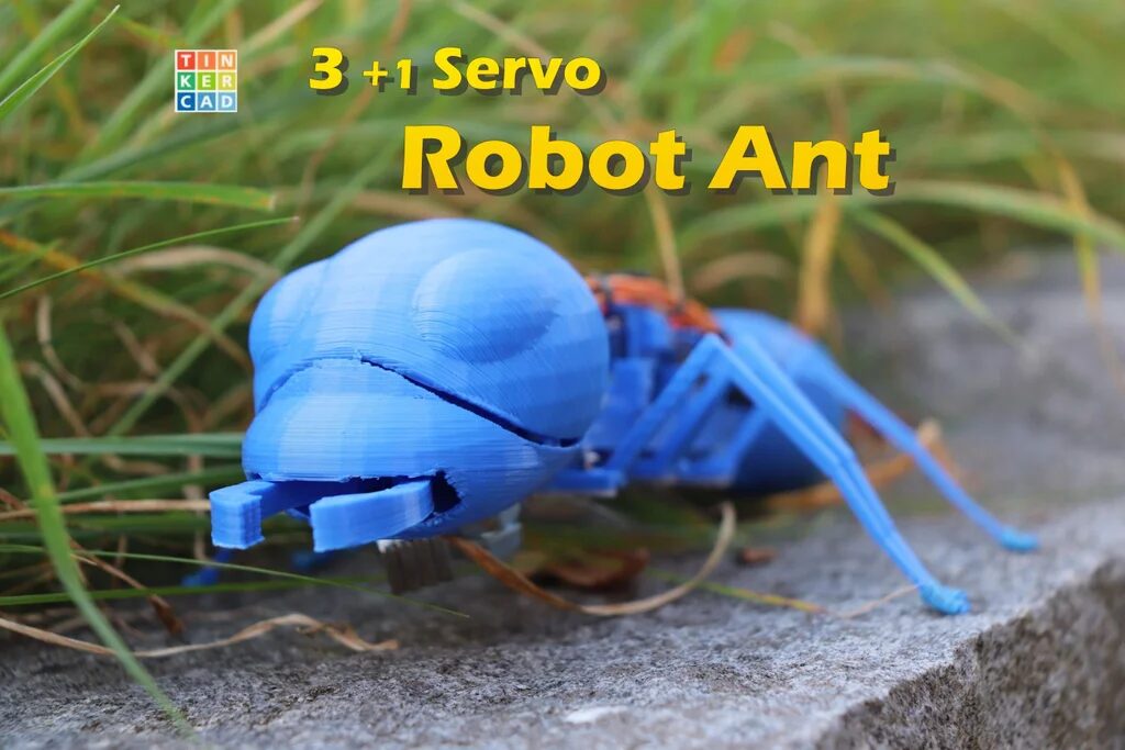
Ants are amazing creatures that require very few resources but can accomplish a lot.

Generally speaking, many six-legged robots require up to three servos per leg, which totals 18 servos, consuming a lot of energy and conflicting with the size of the ant itself.
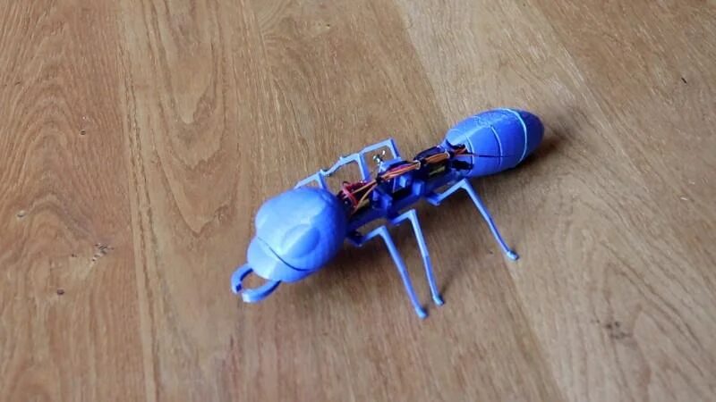
However, this project only uses three servos, a claw, and some mechanical parts to achieve a minimalist ant robot, weighing about 114 grams excluding the battery.
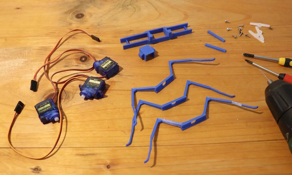
Component List
-
SG90 Servo x 3 -
ESP32/ESP8266 Board x 1 -
Paperclip x Several -
Small Screws x Several -
5V Buck Converter MP1584 x 1 -
9V or 7.4V Lithium Battery x 1
3D Printed Parts
All components were designed using Tinkercad and manufactured with Ultimaker Cura.
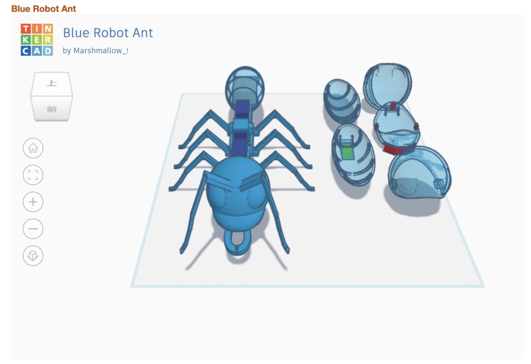
The 3D printing files can be downloaded at the end of the article.
Complete Production Video
Installing the Ant’s Body
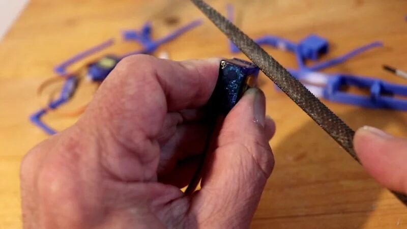
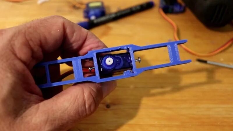
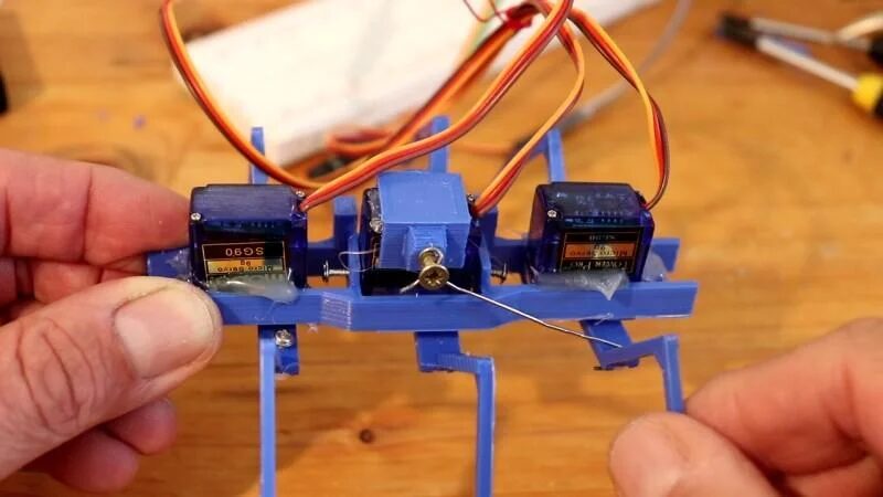
Use pliers or a saw and file to remove all protrusions from the servos.
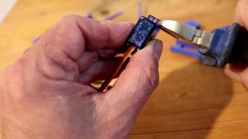
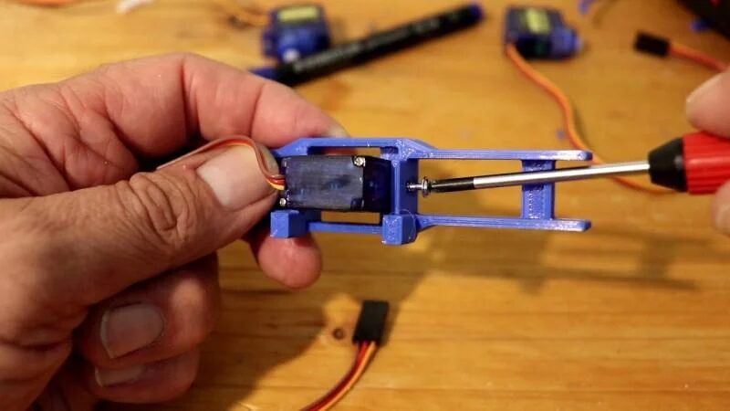
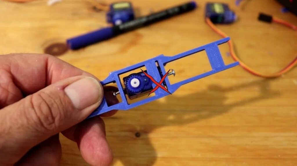
As shown in the picture, secure the printed bottom bracket to servo 2 with two pointed screws; the middle of the servo can swing. It also has a small cover that will be secured later with screws.
Then use hot glue to secure servos 1 and 3 as well as the cover of servo 2.
Before installing the leg parts, the servos must be centered. You can use the program<span>centregs.ino</span> (also available for download at the end) to set the servos to<span>90</span>.
Installing the Servos and Legs
Each servo drives a pair of legs, moving a few degrees back and forth. Servos 1 and 3 will move simultaneously, so you can consider using the same pins on the microcontroller to control them.
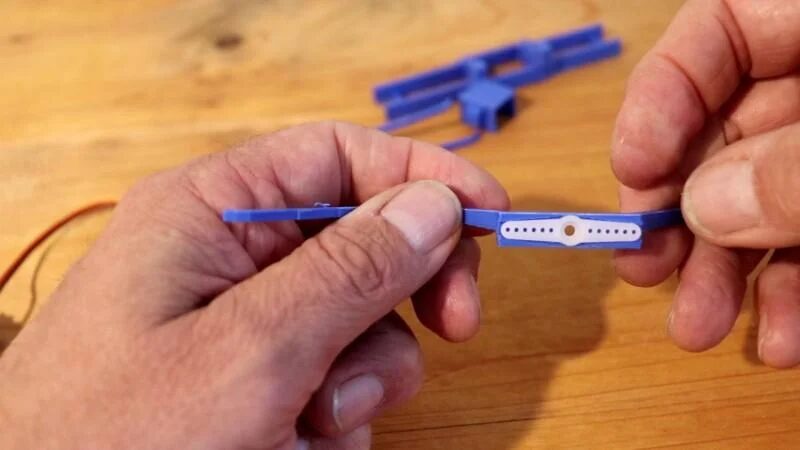
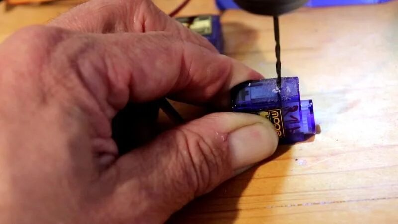
Servo 2 moves in the opposite direction and will pull the legs correctly to the ground while swinging. This swing is generated by the paperclip connected to servo 1. Install each leg to the servo, and you may need to drill holes.
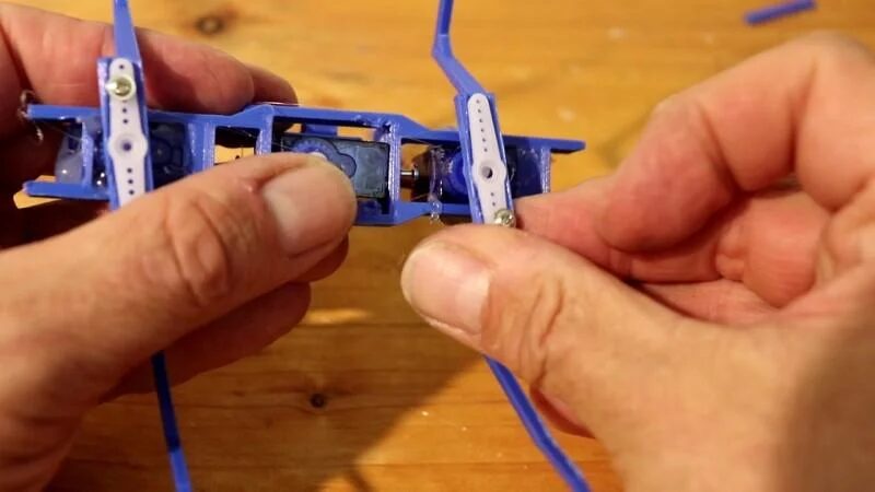
Installing the Mechanical Parts
During installation, use screws and paperclips to connect servo 1 to the cover of servo 2 through the leg mounting plate. This will allow it to tilt at the same angle as servo 1.
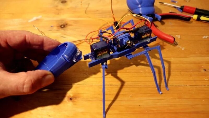
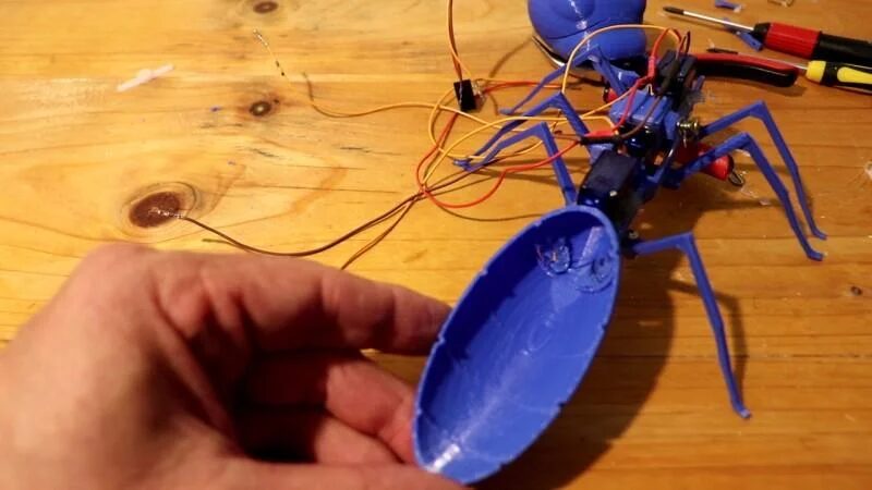
Installing the Head and Claw
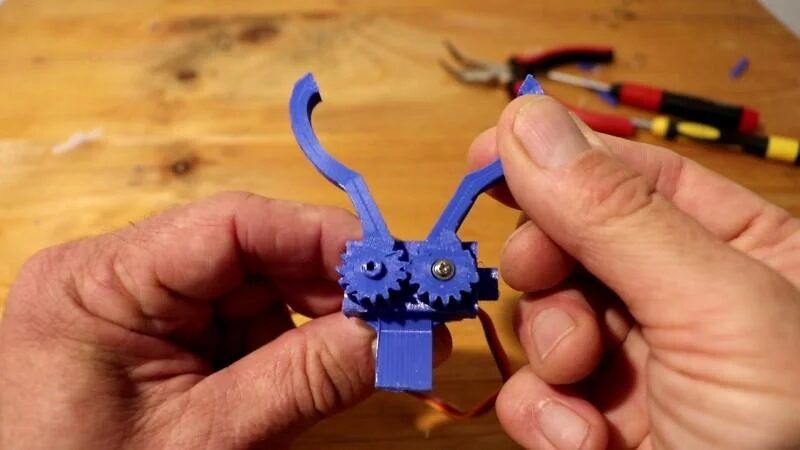
The shape of the claw on the head is not essential, but it has good additional functionality.
Install the servo without arms into the frame. First, set the servo to 90 (refer to<span>centreslegs.ino</span>). Place the appropriate claw part on the gear and secure it with the servo screws. Then place the second part on the shaft.
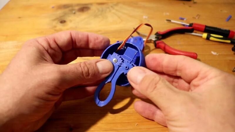
Use hot glue to attach the claw upside down to the head, then close the head. Place the head on top of the torso and glue it securely.
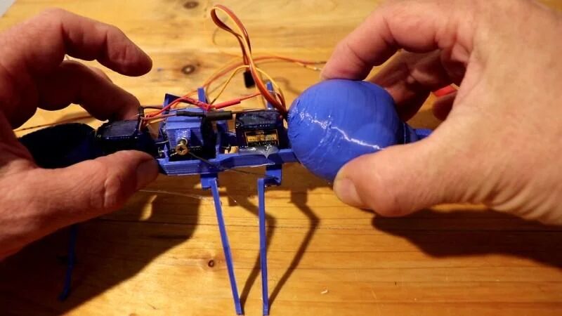
Installing the Tail Battery
Connect the tail to the torso and glue it. It will hold the battery and microcontroller.
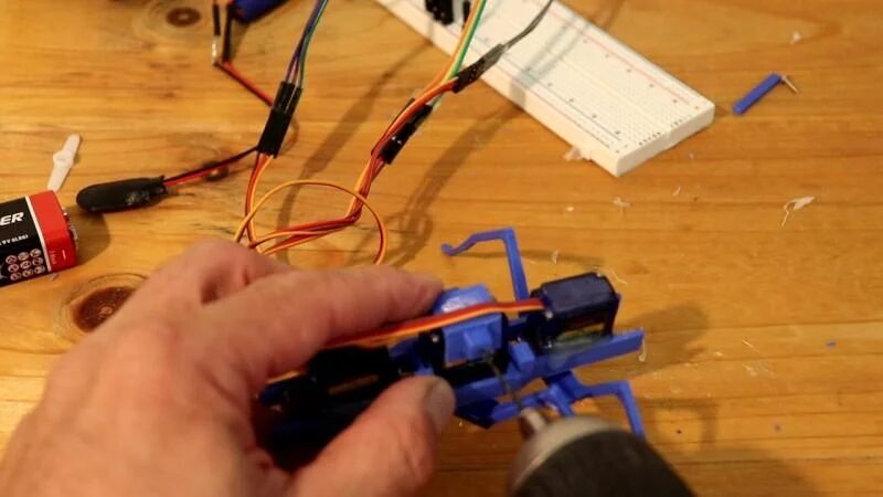
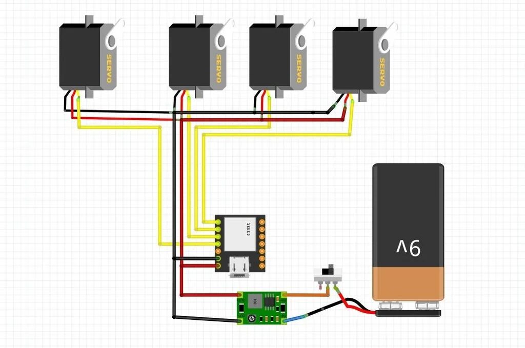
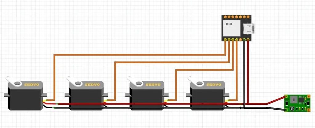
Circuit and Software
A 9V battery can provide enough power for the servos, but the voltage must be reduced to 5V using a buck converter.
 The power for the four servos runs in parallel at 5V, and the data lines connect to the ESP32 development board. No additional connections are necessary. However, it can also connect to sensors or LEDs.
Transfer the file named<span>Blue_Ant-RemoteXY.ino</span> to the ESP32 development board. The remote control is already included in the program. Refer to<span>https://www.instructables.com/Getting-Started-With-ESP32-C3-XIAO/</span>
Servo library for ESP32-C3:<span>ESP32C3Servo</span>
If you are using other ESP32 or ESP8266, you need to change the library at<span>// ************************* Servos</span>:
/*
/ Blue Ant (2023) Markus Opitz
*/
// ************ RemoteXY *************
#define REMOTEXY_MODE__ESP32CORE_BLE
#include <BLEDevice.h>
#include <RemoteXY.h>

// RemoteXY connection settings
#define REMOTEXY_BLUETOOTH_NAME "ESP32-C3_Remote"

// RemoteXY configurate
#pragma pack(push, 1)
uint8_t RemoteXY_CONF[] =   // 43 bytes
  { 255,3,0,0,0,36,0,16,202,1,5,32,17,37,30,30,2,26,24,4,
  128,13,23,37,6,2,78,129,0,3,3,24,6,165,66,108,117,101,32,65,
  110,116,0 };
// this structure defines all the variables and events of your control interface
struct {

    // input variables
  int8_t joystick_1_x; // from -100 to 100
  int8_t joystick_1_y; // from -100 to 100
  int8_t slider_1; // =0..100 slider position
    // other variable
  uint8_t connect_flag;  // =1 if wire connected, else =0
} RemoteXY;
#pragma pack(pop)
// *************************

// ************************* Servos
#include <ESP32C3_Servo.h>   //for ESP32-C3
//#include <Servo.h>         //for ESP8266
//#include <ESP32Servo.h>    //for ESP32-Wroom
Servo servo1;  Servo servo2;  Servo servo3;  // Servo3 is attached to the same pin as Servo1 !!!
Servo Jaws;
int pos1, pos2;    // variable to store the servo position
int centerpos = 90;
int minpos = centerpos-12;
int maxpos = centerpos+12;
int gripper;
//int speed1;


void setup() {
  Serial.begin(115200);
  servo1.attach(2); servo2.attach(3); servo3.attach(4);  //Servo3 can be attached to the same pin as Servo1 //GPIOs on ESP32-C3!
  Jaws.attach(5);
  delay(2);
  servo1.write(centerpos);servo2.write(centerpos-7);servo3.write(centerpos);  //center all servos
  Jaws.write(centerpos);
 delay(3000);

 RemoteXY_Init ();
}


void loop() {
   RemoteXY_Handler ();

    if ((RemoteXY.joystick_1_x) < -30) {
      //Serial.println("<-- left   ");
      left(16);
    }
    if ((RemoteXY.joystick_1_x) > 30) {
      //Serial.println("  right -->");
      right(16);
    }
    if ((RemoteXY.joystick_1_y) < -30) {
      //Serial.println(" backwards ");
      // not yet installed
    }
    if ((RemoteXY.joystick_1_y) > 30) {
      //Serial.println(" ^forward^ ");
      forward(16);
    }
    gripper = map((RemoteXY.slider_1), 0, 100, 75,105);
    Jaws.write(gripper);
    delay(1);
}


void forward(int speed1) {       //speed1 in ms as delay between steps

  for (pos1 = minpos; pos1 <= maxpos; pos1 += 2) {
    pos2 = map(pos1, minpos, maxpos, maxpos, minpos);

    servo1.write(pos1);servo3.write(pos1);Serial.print(pos1);Serial.print("  ");  // front/rear legs
    servo2.write(pos2);  Serial.print(pos2); Serial.println("");                  // center legs
    delay(speed1);
  }

  for (pos1 = maxpos; pos1 >= minpos; pos1 -= 2) {
    pos2 = map(pos1, minpos, maxpos, maxpos, minpos);

    servo1.write(pos1);servo3.write(pos1);      // front/rear legs
    servo2.write(pos2);
    delay(speed1);
  }
}


void right(int speed1) {           //speed1 in ms as delay between steps

  for (pos1 = minpos; pos1 <= maxpos; pos1 += 2) {
    pos2 = map(pos1, minpos, maxpos, maxpos, minpos);

    servo1.write(pos1+10);servo3.write(pos1+10);  // front/rear legs
    servo2.write(pos2+10);                           // center legs
    delay(speed1);
  }

  for (pos1 = maxpos; pos1 >= minpos; pos1 -= 1) {
    pos2 = map(pos1, minpos, maxpos, maxpos, minpos);

    servo1.write(pos1+10);servo3.write(pos1+10);      // front/rear legs
    servo2.write(pos2+10);
    delay(speed1);
  }
}

void left(int speed1) {               //speed1 in ms as delay between steps

    //pos2 = maxpos + 1 -7; //-8 is to correct center position
  for (pos1 = minpos; pos1 <= maxpos; pos1 += 1) {
    pos2 = map(pos1, minpos, maxpos, maxpos, minpos);

    servo1.write(pos1-10);servo3.write(pos1-10);  // front/rear legs
    servo2.write(pos2-10);                           // center legs
    delay(speed1);
  }

  for (pos1 = maxpos; pos1 >= minpos; pos1 -= 2) {
    pos2 = map(pos1, minpos, maxpos, maxpos, minpos);

    servo1.write(pos1-10);servo3.write(pos1-10);      // front/rear legs
    servo2.write(pos2-10);
    delay(speed1);
  }
}
The source code file can be downloaded at the end of the article.
Remote Control
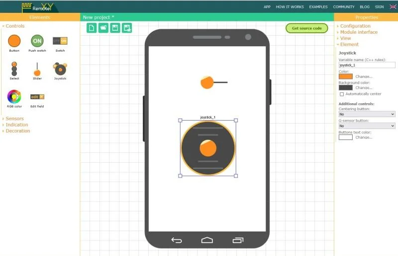
The remote control is included in the code. You can create your own interface for the smartphone remote control at<span>https://remotexy.com/</span> and insert it into the program<span>Blue_Ant-RemoteXY.ino</span>.
For the mobile app, refer to:
<span>https://play.google.com/store/apps/details?id=com.shevauto.remotexy.free</span>
<span>https://apps.apple.com/us/app/remotexy/id1168130280</span>
Install the app on your phone, activate Bluetooth, open<span>RemoteXY</span>, search for and pair with<span>ESP32-C3_Remote</span>.
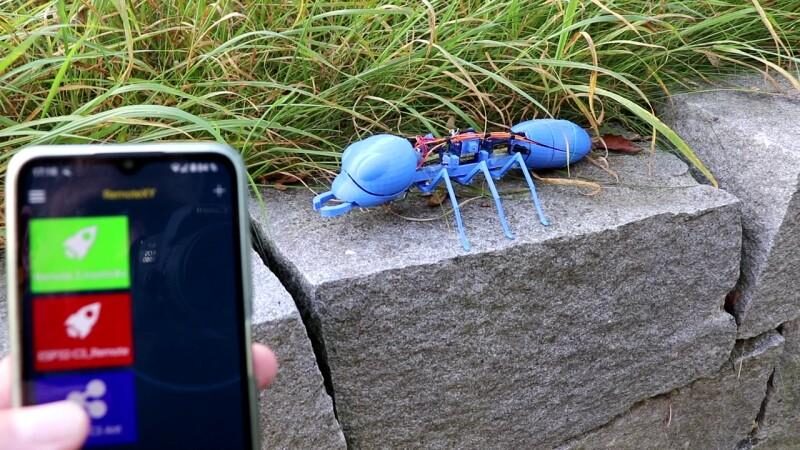
Completion
Now you can start this ant, wait a moment, activate the app, and it can run.
Original article link: https://www.instructables.com/Blue-Robot-Ant/
Project author: Markus Opitz
Please indicate the source information when reprinting
Hardware Arsenal
Click to learn more👆

DFRobot Official Brand Store https://dfrobot.taobao.com/
DFRobot Official Flagship Store https://dfrobot.jd.com/
If you have anything to say, feel free toleave a message!
For the files mentioned in the article, you can click the bottom left cornerRead the original text, or reply “Mechanical Ant” in the public account to get it!
Review of Previous Projects
Understand the entire series of Raspberry Pi in one article!
Learn these 20 Linux commands to master your Raspberry Pi!
Raspberry Pi Cyberdeck with 6 screens, check it out!
Light up the Christmas tree with Raspberry Pi
Build a Raspberry Pi cloud server that you can carry in your pocket!
Make a digital microscope with Raspberry Pi
Spring is here, you need a retro-style Raspberry Pi camera
3D printed Raspberry Pi spider robot
Make a handheld computer with Raspberry Pi and ESP32!
Make a retro game console based on Raspberry Pi Zero
The most comprehensive! How to choose Raspberry Pi expansion boards? A video will do!
Click to read👆