Mechanical Motion Teaching Tool
1. Introduction
This report aims to introduce a physical mechanical motion teaching tool designed based on the Arduino microcontroller, which is intended to help eighth-grade middle school students better understand the core concepts in the chapter on mechanical motion, including reference objects, relative motion, relative rest, uniform linear motion, variable linear motion, and speed measurement. Through this teaching tool, students can deepen their understanding of physical theories in practice, enhancing their learning interest and effectiveness. The physical object of the teaching tool is shown in Figure 1.
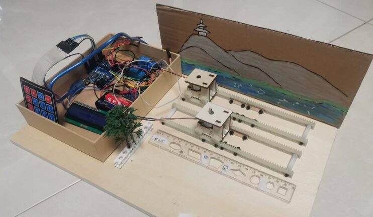
Figure 1 Mechanical Motion Teaching Tool
2. Background and Significance
With the continuous advancement of educational technology and the ongoing innovation of teaching methods, physics experimental teaching plays an increasingly important role in middle school education. As an experimental science, physics experimental teaching not only helps students understand abstract theoretical knowledge but also cultivates their hands-on skills and scientific thinking. However, traditional physics experimental teaching is often limited by the singularity of experimental equipment and the constraints of experimental conditions, making it difficult to meet the diverse learning needs of students.
In the teaching of mechanical motion chapters, students need to understand and master core concepts such as reference objects, relative motion, relative rest, uniform linear motion, variable linear motion, and speed measurement. Understanding these concepts requires students to make intuitive observations and experiences through experiments. However, traditional experimental equipment often only allows for a single experimental demonstration, lacking flexibility and scalability, making it difficult to meet students’ diverse experimental needs.
To overcome the limitations of traditional experimental teaching and improve the effectiveness of physics experimental teaching, this study is dedicated to developing a physical mechanical motion teaching tool designed based on the Arduino microcontroller. This teaching tool aims to integrate various sensors and motor control modules to achieve automated demonstrations of multiple experiments in the mechanical motion chapter. Through programming control, the teaching tool can simulate different motion states while providing real-time data feedback to help students better understand the laws of motion.
Additionally, this teaching tool also has scalability and customizability, allowing teachers to conduct secondary development according to teaching needs, add new experimental projects, or adjust experimental parameters. This flexibility allows the teaching tool to adapt to the learning needs of different students, enhancing the specificity and effectiveness of experimental teaching.
3. Design Content
Experiment 1: The Concept of Reference Object
Based on the concept of reference objects presented on page 17 of the first chapter of the junior high school physics textbook, design a small station scene where the microcontroller controls the motion of a small car to present the concept of reference objects: people always choose a certain object as a standard when judging the motion and rest of an object. If the position of an object changes relative to this standard, it is said to be in motion; if it does not change, it is at rest. This standard object is called a reference object. Through the experiment, one can observe and select trees in the scene as reference objects, or choose two friends on the small car as reference objects to observe phenomena. The design concept map and textbook content are shown in Figure 2.
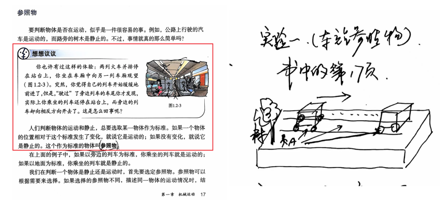
Figure 2 Design Diagram of Experiment 1 and Description in the Book
Experiment 2: Relative Motion
According to the relative motion discussed on page 18 of the textbook: in physics, the motion of an object is relative. The motion state of one object depends on the chosen reference object. If two objects move at the same speed and direction, then relative to one of the objects, the other will appear to be at rest. Design a dual-track device as shown in Figure 3. By simultaneously controlling two small cars on two tracks to move in the same direction and at the same speed, one can observe that the black dots on the bodies of the two small cars do not misalign, allowing for a deep understanding of the concept of relative motion. The design concept map and textbook content are shown in Figure 3.
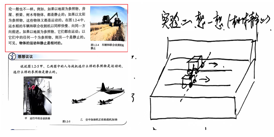
Figure 3 Design Diagram of Experiment 2 and Description in the Book
Experiment 3: Learning Physics Through Hands-On Experience
According to the second question in the hands-on learning section on page 18 of the physics textbook, design a similar scene where the small car is modified into a small boat to observe the small boat moving forward and determine the reference object. This will deepen students’ impression of the question. The design concept map and textbook content are shown in Figure 4.
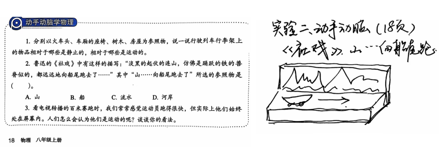
Figure 4 Design Diagram of Experiment 3 and Description in the Book
Experiment 4: The Concept and Measurement of Speed
Based on the speed concept mentioned in section 3 of the textbook, design a track with a ruler in front. By controlling the small car to move forward and stop, the microcontroller screen displays the time taken for that segment of the journey, and the speed of the small car is calculated using a formula. The design concept map and textbook content are shown in Figure 5.
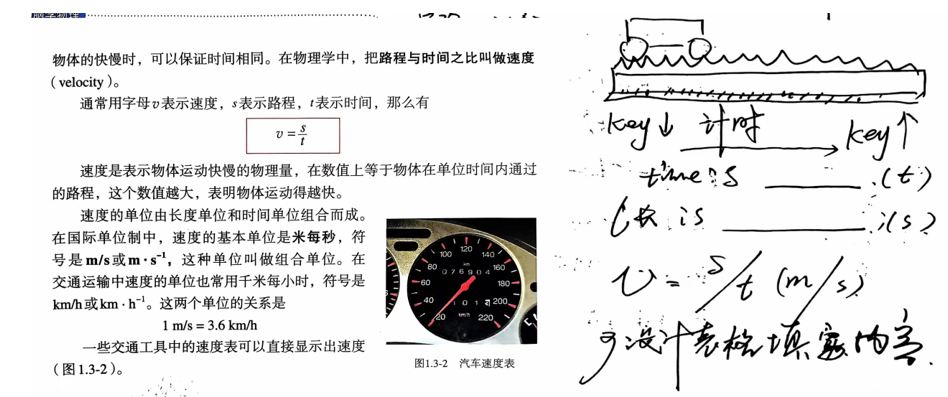
Figure 5 Design Diagram of Experiment 4 and Description in the Book
Experiment 5: Uniform Linear Motion and Variable Linear Motion
According to the description of the two types of motion on page 20 of the textbook, design to observe the variable motion of vehicles and linear motion to deepen familiarity with this knowledge point.
4. Design Process
According to the task requirements, the design is described in five parts: overall scheme, mechanical design of the small car, circuit design, scene design, and software programming.
1. Overall Project Design
This project is a multidisciplinary cross-application based on the application scenario, circuit design, and mechanical design, by designing a small scene that includes the aforementioned experiments, such as a rockery background and vehicle tracks, etc., to make the scene more concrete.
By designing the Arduino microcontroller to control the small car, the motion of the small car is based on the control of a DC motor. The control power is transmitted to the gear through a worm gear, and the horizontal movement on the rack is completed through the gear.
Ultimately, the project is completed through programming.
2. Mechanical Design of the Small Car
The small car converts power to the small car’s gears (wheels) through the principle of worm gears. A 3D-printed rack serves as the track to allow the small car to move smoothly. The entire small car is supported by wooden boards to stabilize it. The design of the small car is shown in Figure 6.
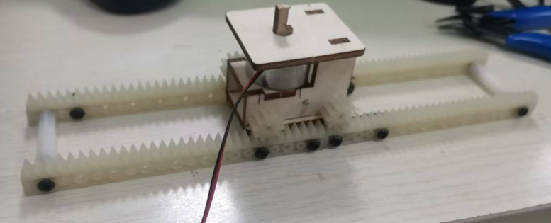
Figure 6 Small Car Design
3. Arduino Circuit Control Design
(1) Driving the DC Motor
To control the motion direction of the small car, the DC motor used requires a relay circuit switch, and the speed of the small car needs to be controlled via PWM. Therefore, the design of the DC motor driving circuit is shown in Figure 7.
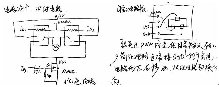
Figure 7 Hardware Circuit Involved
(2) 4X4 Keyboard
The control of the small car relies on button control. This project uses a 4X4 keyboard with a total of 16 keys. This project only uses keys 1-4. The functions of the keys are shown in Table 1.
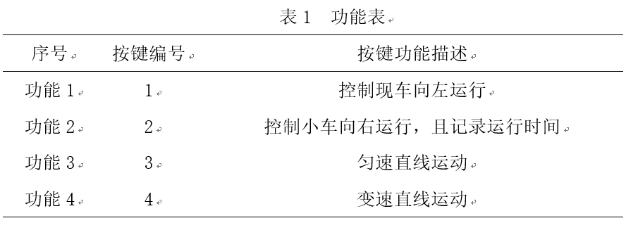
Table 1 Function Table
(3) LCD Screen Display
The second function of the small car is to record the time during operation. When button 2 is pressed, timing starts; when button 2 is released, timing stops, and the time value is displayed on the screen.
4. Application Scene Design
The track is installed on a wooden board, and the circuit is placed in a box, designing a small scene as shown in Figure 8.
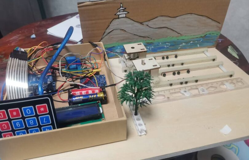
Figure 8 Scene Production
5. Software Programming
Once the hardware design of the teaching tool is complete, software programming can realize the aforementioned functions. The source code of the software (partial functional program) is shown in Figure 9.
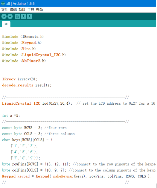
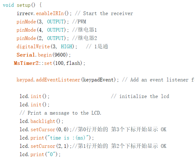
Figure 9 Partial Program Diagram
5. Teaching Tool Testing
1. Reference Object Demonstration
During the test, the teaching tool simulated the motion states of different objects under the selected reference object through Arduino-controlled LED lights and mechanical structures. Students could intuitively understand the impact of reference objects on the motion state of objects by observing the flashing LED lights and the movement of mechanical components. The test results showed that the choice of reference objects had a significant impact on the description of the motion state of objects, and the demonstration effect of the teaching tool was clear and accurate. The effect is shown in Figure 10.
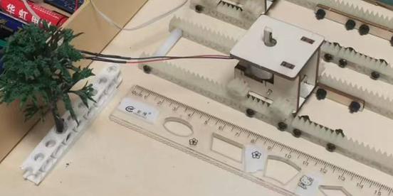
Figure 10 Concept of Reference Object in Experiment 1
2. Relative Motion Demonstration
The teaching tool utilized two independently controlled mechanical components to simulate the relative motion between two objects. By adjusting the parameters in the Arduino program, demonstrations of relative motion at different speeds and directions could be achieved. During the test, students observed changes in the relative motion state between the two objects, deepening their understanding of the concept of relative motion. The test results indicated that the teaching tool could accurately and intuitively display relative motion phenomena, as shown in Figure 11.
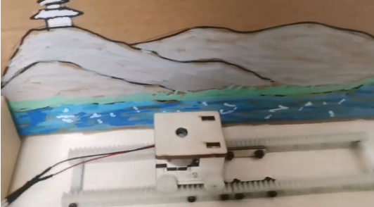
Figure 11 Experiment Two in the Book
3. Relative Rest Demonstration
In the relative rest demonstration, the teaching tool fixed one mechanical component as a reference object, while the other component maintained a state of relative rest with respect to the reference object under specific conditions. Through precise control of the Arduino, the relative rest of the two objects under specific conditions was achieved. The test results showed that students could clearly observe the phenomenon of relative rest and understand the underlying physical principles, as shown in Experiment 12.
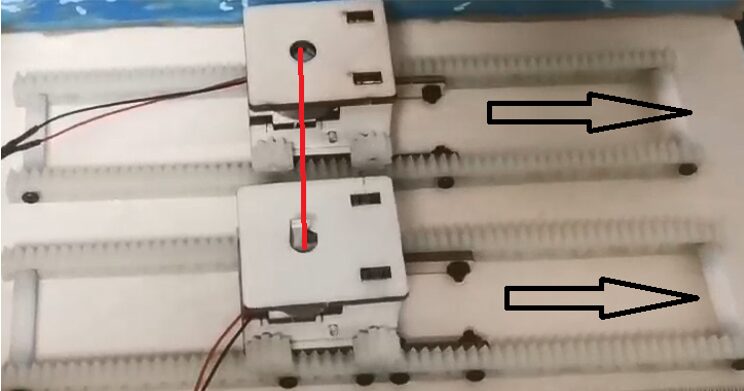
Figure 12 Experiment Two Relative Rest
4. Uniform Linear Motion and Variable Linear Motion Demonstration
The teaching tool demonstrated uniform linear motion and variable linear motion by controlling the speed and acceleration of mechanical components. In the test, students observed the motion trajectories of mechanical components at different speeds and the impact of acceleration changes on motion states. The test results indicated that the teaching tool could accurately and vividly demonstrate the characteristics of uniform linear motion and variable linear motion.
5. Speed Measurement
The teaching tool is equipped with timing and Arduino programs, with a ruler installed on the desk. It can measure and record the displacement distance of mechanical components in real-time. During the test, students learned the basic principles and methods of speed measurement by observing the real-time display of speed measurement results. The test results showed that the speed measurement function of the teaching tool was accurate and reliable, providing valuable experimental data support for students, as shown in Figure 13.
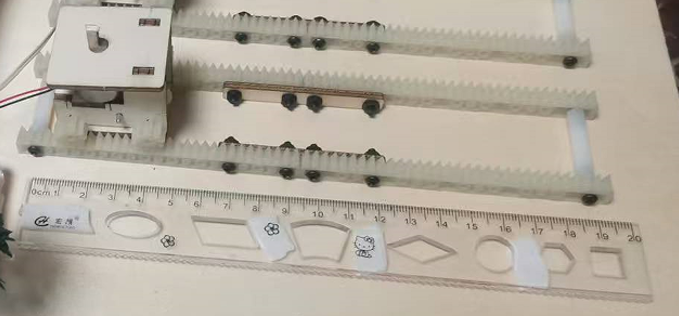
Figure 13 Measurement of Speed in Experiment Four
6. Conclusion
By using this teaching tool for experimental demonstrations, students can intuitively observe the changes of objects under different motion states, deepening their understanding of mechanical motion concepts. Meanwhile, the real-time data feedback function of the teaching tool also helps students better grasp the methods and techniques of speed measurement.
This project successfully implemented demonstrations of multiple experiments in the chapter on mechanical motion in eighth-grade physics based on the Arduino microcontroller design. The teaching tool has the advantages of rich functions, easy operation, and accurate data, effectively enhancing students’ learning interest and experimental effectiveness. In the future, we will continue to improve the functions and performance of the teaching tool to provide better auxiliary tools for physics teaching.
Recommended Reading

[Autumn Enrollment] Enrollment Guide for the 2024 Autumn Class of Jinzhong Youth Activity Center!

[Eighth Anniversary] Eighth Anniversary Celebration Series Activities “To Observe” Children’s Art Exhibition

[Research and Practice] “Taihang Mountain” Paleontology Geological Survey Research and Study Excursion Concludes

[Research and Practice] “Touch Nature, Explore the Unknown” Kubuqi Desert Research and Practice Activity
Art knows no bounds, childhood is no different. Let children walk in art and grow in practice. Jinzhong Youth Activity Center welcomes you!
◆ ◆ ◆ ◆ ◆
Text | Bai Yuanming
Editor | Mao Ruigang
Reviewer | Liu Jiaxiang

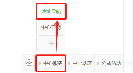
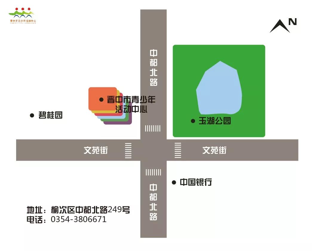
Public account left bottom – [Center Services] – [Address Navigation]