
4. MT8852B Supported AoA/AoD RF Testing Functions
4.1 Output Power
The Tx level variation in the Constant Tone Extension (CTE) section will affect the phase detection accuracy. This measurement calculates the average power and peak power values using traditional output power measurement methods and determines if they fall within the target measurement range. Figure 7 shows the actual measured values of AoA transmission.
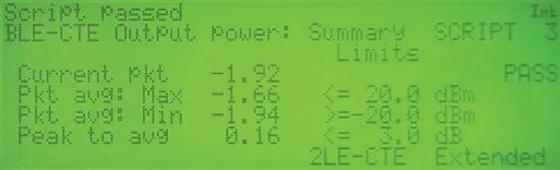
Figure 7 Output Power Measurement Interface
4.2 Carrier Frequency Offset and Drift
Unlike array antenna synchronized reception, the time-division reception signal through antenna switching is used to calculate the phase difference. Therefore, to maintain phase difference accuracy, the CTE section must comply with the specified frequency and reduce frequency deviation.
Traditional carrier frequency offset is measured based on the preamble, while traditional drift is measured based on time variation. Here, the measurement is conducted on the constant tone extension.
By measuring the 16 µs in the preamble and payload, the average frequencies f0 and fp are obtained (as shown in Figure 8). Additionally, the frequency mean of the constant tone extension (CTE) must be measured every 16 µs (as shown in Figure 9).
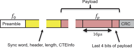
Figure 8 CTE Reference Frequency (f0, fp)

Figure 9 CTE Frequency Drift
Then, the average absolute frequency shift Δf1avg from the Payload part is used to calculate fsi(=f3maxi – Δf1avg) to determine if it meets the following:
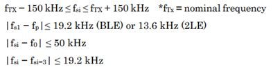
Figure 10 Shows the MT8852B Measurement Screen for This Use Case. To comply with the specifications, the MT8852B strictly checks symbol timing to ensure each frequency measurement position is accurate. This method is similar to traditional carrier frequency offset and drift measurements.

Figure 10 Carrier Frequency Offset and Drift Measurement Diagram
4.3 Tx Power Stability
Since AoD transmission uses time-division for antenna switching, the switching timing and response will affect the calculation of phase difference. Therefore, the CTE must transmit at a stable power level. Additionally, power variation between antennas must be minimal.
As shown in Figure 2, the CTE has three intervals called Reference period, Switch slot, and Sample slot, used for antenna switching timing. Antenna switching must be completed within the switching slot. If the antenna switching exceeds the Switch slot interval, the Reference period and Sample slot intervals will be affected.
When assessing Tx power stability, the ratio of the average power PREF,AVE to the maximum deviation range of the reference period PREF,DEV must meet the following conditions:
-
PREF,DEV/PREF,AVE < 0.25
-
Pn,DEV/Pn,AVE < 0.25
Figures 11 and 12 show screenshots of this measurement item. When using the MT8852B to measure each power, the position of each measurement interval is accurately determined based on symbol timing to comply with the specifications. As shown in Figure 12, the worst-case results of Pn,DEV/Pn,AVE for the Sample slot are displayed on the screen for easy assessment of whether all sampling slots meet the requirements.
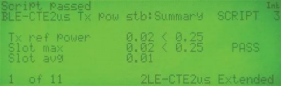
Figure 11 Tx Power Stability Measurement (Reference Period, Slot Typical Values)
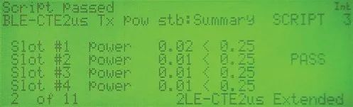
Figure 12 Tx Power Stability Measurement (Each Slot)
4.4 BLE Packet Generation Extension
MT8852B provides BLE packet generation capabilities to output any low-power signals. This function has been extended to output AoA/AoD signals. The setup screen is shown in Figure 13. By setting the CTE type and switching time length parameters, users can conduct related tests under the required measurement conditions, including AoA and AoD sensitivity tests not specified in RF testing standards.
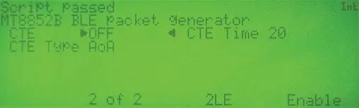
Figure 13 BLE Packet Generation Setup (CTE Settings)
5. Conclusion
This article introduces the direction-finding function in the MT8852B and lists some test cases. As a member of the Bluetooth Alliance, Anritsu will continue to support the development of new Bluetooth technologies and standards to provide comprehensive solutions for customers’ product development and production.
References:
-
Bluetooth Core Specification revision v5.2 (2019-12) -
Bluetooth Radio Frequency(RF)/Bluetooth® Test Suite revision RF.TS.p30 edition 2 (2020-1) -
Bluetooth Radio Frequency Physical Layer (RF PHY)/Bluetooth® Test Suite revision RF-PHY.TS.p15 (2020-1) -
Bluetooth Core Specification Version 5.2 Feature Overview version 1.0 (2020-01)
About Anritsu
– Scan to Follow –
Cross Testing

Crossing Limits

5G & IoT | RF Microwave | High-Speed Signal | Wireless Communication | Optical and Digital Communication
Customer Service Hotline 400-879-6892