Developing software that satisfies users is not an easy task; software architects must comprehensively grasp various requirements, weigh potential conflicts between them, and categorize different requirements for satisfaction. This article discusses the complexity of understanding different types of requirements and demonstrates, through specific case analysis, how to perform architectural design using the RUP 4+1 view method, ensuring that important requirements are met.
Call for a Multi-View Approach to Architecture Design
When inspiration strikes, one might think of a way to put an elephant in a refrigerator, which is certainly good. However, it is unrealistic to rely on inspiration for every architectural design strategy—we need guidance from systematic approaches.
The need for a multi-view approach to architecture design fundamentally arises from the complexity of requirement types. Let’s start with an example from the engineering field. For instance, when designing a bridge across a river, we would consider the “functional requirement” of “connecting north and south road traffic,” leading to an initial design of an idealized road bridge supported by piers; then we must consider the “constraints” faced during construction, such as “not affecting the passage of ten-thousand-ton vessels under the bridge,” which refines the design to specify the height of the piers and the spacing between them; additionally, we must consider the “quality attributes during the bridge’s service life,” such as ensuring the bridge remains stable in turbulent river flows by building the piers deep into the rock layer, integrating with the earth; in fact, the “quality attributes during construction” are also worth considering, for example, measures to ensure “ease of construction” during the design process.
Similar to the functional requirements, constraints, quality attributes during service life, and quality attributes during construction in engineering, the types of requirements for software systems are also quite complex, as illustrated in Figure 1.
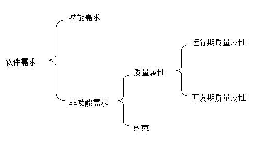
Figure 1 Complexity of Software Requirement Classification
Supermarket System Case: Understanding the Complexity of Requirement Types
Examples are the best teachers. To better understand the complexity of software requirement types, let’s analyze a practical example. In Table 1, we list a subset of requirements for a typical supermarket system, clearly showing that requirements can be divided into two main categories: functional requirements and non-functional requirements.
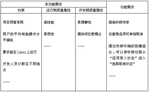
Table 1 Supermarket System Case: Understanding the Complexity of Requirement Types
In simple terms, functional requirements refer to “what the software does and what it needs to accomplish.” It is also best practice to grasp the hierarchy of functional requirements. For example, the supermarket owner wants the software to “improve checkout efficiency.”
Thus, you might need to provide a series of functions to facilitate this goal, such as the “ability to cancel any item individually” function for cashiers, which aids in improving checkout efficiency (I once had a painful experience at a supermarket where I had to cancel an entire order and rescan a cart full of items).
Specifically, for this supermarket system, the system analyst may decide that the specific function to provide is: through a combination of keys on the checkout terminal, the cashier can switch from the “item-by-item entry state” to the “select cancel state,” thus canceling a specific item.
From the above example, we are also surprised to find that non-functional requirements—a category of requirements often overlooked—are very broad and extremely important. Non-functional requirements can be further divided into three categories:
Constraints. Developing software that satisfies users is not an easy task, and fully understanding the constraints faced by the software system to be designed can help you take a step closer to success. Constraint requirements include both enterprise-level business considerations (e.g., “limited project budget”) and actual situations at the end-user level (e.g., “users have a low average computer operation level”); they may also include specific technical requirements (e.g., “must run on Linux”) and consider the real situation of the development team (e.g., “developers are dispersed in different locations”). These constraint requirements significantly impact architectural design; for example, if constrained by a “limited project budget,” architects should avoid selecting expensive technologies or middleware and, considering that developers are dispersed in different locations, should emphasize the reasonableness and loose coupling of software module responsibilities.
Runtime Quality Attributes. This type of requirement mainly refers to the quality level exhibited by the software system during its operation. Runtime quality attributes are crucial because they directly affect customer satisfaction with the software system; most customers will not accept poorly performing software systems. Common runtime quality attributes include usability, performance, scalability, continuous availability, robustness, and security. In our supermarket system case, users have specific performance requirements (true performance requirements should be quantified, which our Table 1 does not reflect); they cannot tolerate delays exceeding two seconds for total amounts.
Development Quality Attributes. Some items in this category of non-functional requirements are often remembered, but many people do not realize the differences between the impacts of “development quality attributes” and “runtime quality attributes” on architectural design. Development quality attributes are of utmost concern to developers, and the goals should be determined based on the specific circumstances of the project, while overengineering can incur additional costs.
What is a Software Architecture View?
So, what is a software architecture view? Philippe Kruchten writes in his book “The Rational Unified Process: An Introduction”:
An architecture view is a simplified description of the system as seen from a particular perspective or point, covering a specific aspect of the system while omitting entities unrelated to this aspect. In other words, the content and decisions that architecture must encompass are too numerous for the human brain to handle in one go; thus, a “divide and conquer” approach is adopted to design from different perspectives; at the same time, it facilitates understanding, communication, and archiving of software architecture.
It is worth noting that most books emphasize that the multi-view approach is a method for archiving software architecture; however, this is not entirely true. The multi-view approach is not only an archival technique but also a thinking method that guides us in architectural design.
Philippe Kruchten’s 4+1 View Method
In 1995, Philippe Kruchten published a paper titled “The 4+1 View Model of Architecture” in IEEE Software, which garnered significant attention in the industry and was eventually adopted by RUP, as shown in Figure 2.
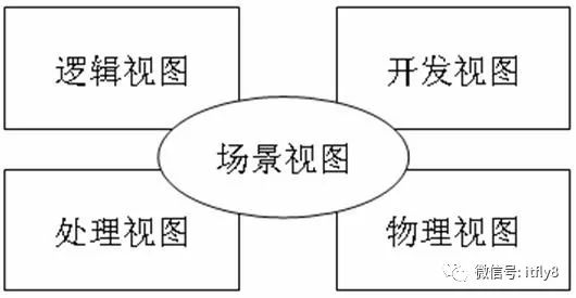
Figure 2 Philippe Kruchten’s 4+1 View Method
This method’s different architectural views carry different architectural design decisions, supporting different goals and purposes:
Logical View: When using an object-oriented design approach, the logical view is the object model.
Development View: Describes the static organization of the software in the development environment.
Process View: Describes the design aspects of concurrency and synchronization in the system.
Physical View: Describes how the software maps to hardware, reflecting the design of the system in terms of distribution.
Applying the 4+1 View Method: Architectural Design for Different Requirements
As mentioned earlier, developing software that satisfies users is not an easy task; software architects must comprehensively grasp various requirements, weigh potential conflicts between them, and categorize different requirements for satisfaction.
Philippe Kruchten’s 4+1 view method provides a solid foundation for software architects to “conquer requirements one by one,” as illustrated in Figure 3.
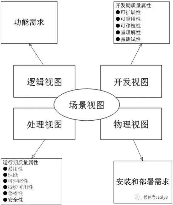
Figure 3 Architectural Design for Different Requirements Using the 4+1 View Method
Logical View. The logical view focuses on functionality, including not only user-visible functions but also the “auxiliary functional modules” necessary to achieve user functions; these may include logical layers, functional modules, etc.
Development View. The development view focuses on packages, including not only the source code to be written but also third-party SDKs and ready-made frameworks, libraries, and the system software or middleware on which the developed system will run. There may be a certain mapping relationship between the development view and the logical view: for example, logical layers generally map to multiple packages.
Process View. The process view focuses on runtime concepts such as processes, threads, and objects, as well as related concurrency, synchronization, and communication issues. The relationship between the process view and the development view is that the development view generally emphasizes the static dependencies of packages at compile time, while these will manifest as objects, threads, and processes at runtime, focusing on the interactions of these runtime units.
Physical View. The physical view focuses on how the “target program and its dependent runtime libraries and system software” are ultimately installed or deployed to physical machines, and how to deploy machines and networks to meet the software system’s reliability and scalability requirements. The relationship between the physical view and the process view is that the process view particularly focuses on the dynamic execution of the target program, while the physical view emphasizes the static positioning of the target program; the physical view comprehensively considers the mutual influences between the software system and the entire IT system.
Overview of the Device Debugging System Case
The following sections of this article will study a case: a debugging system for a certain model of equipment.
Through this system, device debug personnel can check the device status (the status information of the device is collected in real-time by a dedicated data collector) and send debugging commands. The use case diagram for this system is shown in Figure 4.
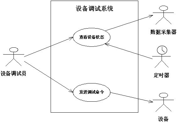
Figure 4 Use Case Diagram of the Device Debugging System
After close cooperation between the developer and the client, the finalized requirements can be summarized in Table 2.
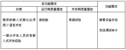
Table 2 Requirements for the Device Debugging System
Next, we will apply the RUP-recommended 4+1 view method to perform architectural design from different views, categorizing different requirements for satisfaction.
Logical View: Designing Architecture to Meet Functional Requirements
First, preliminary design is conducted based on functional requirements, performing coarse-grained responsibility allocation. As shown in Figure 5.
The application layer is responsible for displaying the device status and providing a simulation console for users to send debugging commands.
The application layer interacts with the communication layer and the embedded layer, but the application layer is unaware of the communication details.
The communication layer is responsible for implementing a dedicated “application protocol” on top of the RS232 protocol.
When the application layer sends a protocol packet containing debugging instructions, the communication layer is responsible for passing it to the embedded layer according to the RS232 protocol.
When the embedded layer sends raw data, the communication layer interprets it as an application protocol packet and sends it to the application layer.
The embedded layer is responsible for the specific control of the debugging device and for frequently reading device status data from the data collector.
The physical specifications of the device control instructions are encapsulated within the embedded layer, and the specifics of reading from the data collector are also encapsulated within the embedded layer.
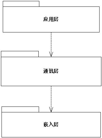
Figure 5 Logical View of the Device Debugging System Architecture
Development View: Designing Architecture to Meet Development Quality Attributes
The development view of the software architecture should provide practical guidance for developers. Any design decisions affecting the overall architecture should be made during architectural design; if these decisions are “missed” and only discovered during large-scale parallel development, it may lead to numerous “programmers making on-the-fly decisions,” which will inevitably decrease software quality and may even lead to project failure.
Among these, the choice of which ready-made frameworks, third-party SDKs, and middleware platforms should be determined by the development view of the software architecture. Figure 6 shows a portion of the software architecture development view for the device debugging system: the application layer will be implemented based on MFC, while the communication layer uses a third-party SDK for serial communication.
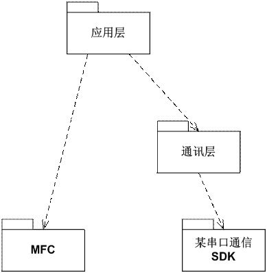
Figure 6 Development View of the Device Debugging System Architecture
Now, let’s discuss constraint requirements. Constraints should be design limitations that every architectural view should focus on and adhere to. For example, considering the constraint that “some developers have no embedded development experience,” the architect must specify how the system’s target program is compiled: Figure 7 shows how the entire system’s desktop portion target program pc-moduel.exe and the embedded module rom-module.hex are compiled. This global description undoubtedly provides a tangible understanding for inexperienced developers, aiding in a more comprehensive understanding of the system’s software architecture.
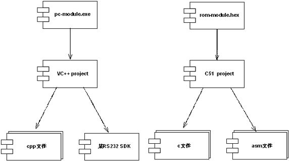
Figure 7 Development View of the Device Debugging System Architecture
Process View: Designing Architecture to Meet Runtime Quality Attributes
Performance is a quality level exhibited by the software system during its operation, generally measured by system response time and throughput. To meet high-performance requirements, software architects should analyze and design based on the software’s runtime conditions, which is the goal of the software architecture’s process view. The process view focuses on runtime concepts such as processes, threads, and objects, as well as related concurrency, synchronization, and communication issues. Figure 8 shows the process view of the device debugging system architecture.
As can be seen, to satisfy high-performance requirements, the architect has adopted a multi-threaded design:
The thread in the application layer represents the main program’s operation, directly utilizing MFC’s main window thread. Whether for user interaction or incoming serial data, asynchronous event handling is adopted, eliminating any “busy waiting” and unnecessary time wastage, while also shortening system response time.
The communication layer has an independent thread controlling the “up and down” data and sets up a data buffer, allowing data reception and processing to be relatively independent, thus preventing data reception from stalling due to temporary busy processing, increasing system throughput.
In the embedded layer design, events are triggered through clock interrupts and RS232 port interrupts to achieve polling and data transmission purposes.
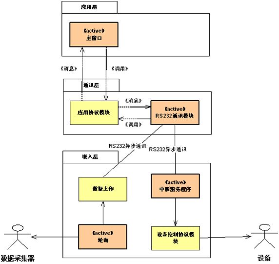
Figure 8 Process View of the Device Debugging System Architecture
Physical View: Architecture Decisions Related to Deployment
Software must ultimately reside, be installed, or deployed on hardware to operate, and the physical view of software architecture focuses on how the “target program and its dependent runtime libraries and system software” are ultimately installed or deployed on physical machines, and how to deploy machines and networks to meet the software system’s reliability and scalability requirements. The physical architecture view shown in Figure 9 expresses the mapping relationship between the software and hardware of the device debugging system. It can be seen that the embedded part resides in the debugging machine (which is a dedicated single-board computer), while the PC runs in the form of a common desktop executable program.
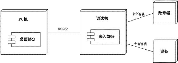
Figure 9 Physical View of the Device Debugging System Architecture
We may also express the specific target modules and their communication structure more clearly based on the physical architecture view as shown in Figure 10.
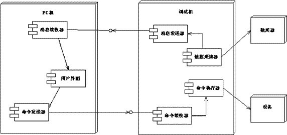
Figure 10 Physical View of the Device Debugging System Architecture
Summary and Explanation
What is said to be the essence of the matter. A deep understanding of the complexity of software requirement classification, clearly distinguishing functional requirements, constraints, runtime quality attributes, development quality attributes, and other types of requirements is the “essence” because the impact of each type of requirement on architectural design is completely different. This article demonstrates, through specific case analysis, how to perform architectural design using the RUP 4+1 view method to ensure that important requirements are met.
This article focuses on explaining the method, thus omitting many specific issues in architectural design, and the model provided for explaining the architectural design scheme has also been simplified. Please note this, dear readers.
Source: http://www.uml.org.cn/zjjs/201412262.asp