Click the blue text above to follow us
Embedded Training – Choose Jufeng Smart Link
1. Definition
UART (Universal Asynchronous Receiver/Transmitter) is a widely used serial communication protocol for transmitting data asynchronously between devices. It does not require a shared clock signal but relies on pre-agreed parameters (such as baud rate) for communication.
Functions and Features
A basic UART system requires only three signals to provide robust mid-speed full-duplex communication: Tx (transmitted serial data), Rx (received serial data), and ground.
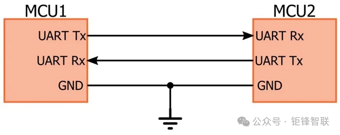
Compared to other protocols like SPI and I2C, it does not require a dedicated clock signal to synchronize data transmission, which is determined by its unique communication mechanism.
Asynchronous Communication: The sender transmits data based on a preset baud rate (the number of bits transmitted per second), while the receiver also receives and parses data at the same baud rate. This mechanism allows UART to perform effective data transmission without external clock signals.
Internal Clock Control: Although UART does not require external clock signals, it still relies on internal clock signals to control data transmission and reception. These internal clock signals are provided by the UART hardware module itself to generate the timing for sending and receiving data. However, these internal clock signals do not need to be transmitted to other devices via external lines but only function within the local device.
2. Working Principle
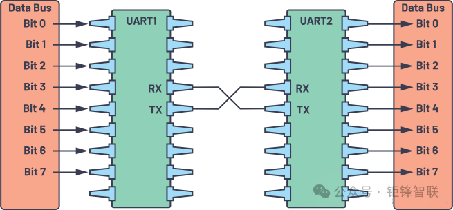
The UART receiving data is received from the data bus. The data bus is used to send data to the UART from other devices such as CPUs, memory, or microcontrollers. Data is transmitted in parallel from the data bus to the transmitting UART. After the transmitting UART retrieves the parallel data from the data bus, it adds a start bit, a parity bit, and a stop bit to create a data packet.
Next, the data packet is serially output bit by bit on the Tx pin. The receiving UART reads the data packet bit by bit on its Rx pin. Then, the receiving UART converts the data back to parallel form and removes the start bit, parity bit, and stop bit. Finally, the receiving UART transmits the data packet in parallel to the receiving end’s data bus:
The transmitting UART does not use a clock signal but adds start and stop bits to the data packet being transmitted. These bits define the beginning and end of the data packet, allowing the receiving UART to know when to start reading these bits.
When the receiving UART detects the start bit, it begins reading the input bits at a specific frequency known as the baud rate. The baud rate is a measure of data transmission speed, expressed in bits per second (bps). Both UARTs must operate at approximately the same baud rate. The baud rates between the transmitting and receiving UART can only differ by about 10% before the timing of the bits becomes misaligned.
Both UARTs must also be configured to send and receive the same data packet structure.
Key Points to Understand About UART
Baud Rate
The baud rate indicates the number of symbols transmitted per second (unit: bps, bits per second), determining the rate of data transmission.
Common values: 9600, 19200, 38400, 57600, 115200 bps, etc.
Importance: The baud rate of the sender and receiver must be consistent (baud rate error must be controlled within an acceptable range).
Common Issues: Baud rate mismatches can lead to garbled data; high-frequency clock errors can accumulate and cause communication failures.
3. Protocol Frame
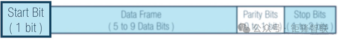
In UART, the transmission mode is in the form of packets. The mechanism connecting the transmitter and receiver includes the creation of serial data packets and the control of physical hardware lines. A data packet consists of a start bit, data frame, parity bit, and stop bit.

3.1 Start Bit
The start bit is the first bit of a single-byte UART transmission. It indicates that the data line is leaving its idle state.
When no data is being transmitted, the UART data transmission line typically remains at a high voltage level. To start data transmission, the transmitting UART pulls the transmission line from high to low and holds it for one clock cycle. When the receiving UART detects the high-to-low voltage transition, it begins reading the bits in the data frame at the frequency corresponding to the baud rate.
The start bit is an overhead bit: it facilitates communication between the receiver and transmitter but does not transmit meaningful data.
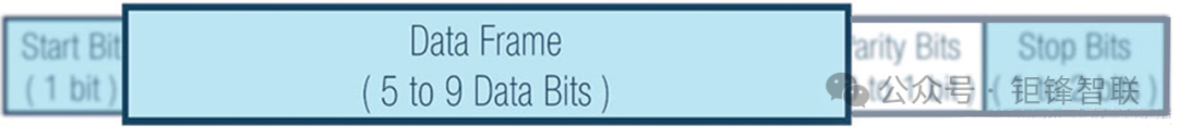
3.2 Data Frame
The data bits contain the actual data being transmitted. If parity is used, the length of the data bits is 5 to 8 bits; if no parity is used, the length is 5 to 9 bits. Generally, the data bits are 8 bits long, and data is sent starting from the least significant bit, with the most significant bit following.
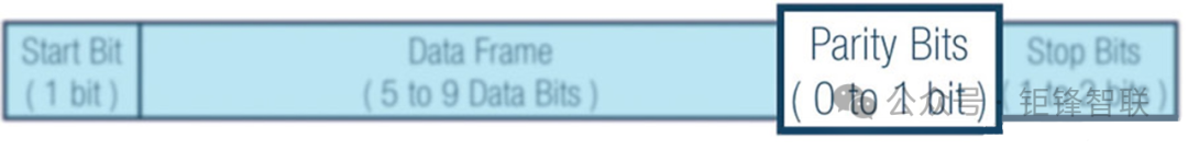
3.3 Parity Bit
Parity describes whether the number of bits is even or odd. The parity bit is a way for the receiving UART to determine if any data has changed during transmission. Bits can change due to electromagnetic radiation, mismatched baud rates, or long-distance data transmission.
After the receiving UART reads the data frame, it counts the number of bits that are 1 and checks whether the total is even or odd. If the parity bit is 0 (even parity), the number of 1s or logical high bits in the data frame should total to an even number. If the parity bit is 1 (odd parity), the number of 1s or logical high bits in the data frame should total to an odd number.
When the parity bit matches the data, the UART knows that the transmission is error-free. However, if the parity bit is 0 and the total is odd, or the parity bit is 1 and the total is even, the UART knows that the bits in the data frame have changed.
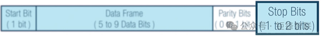
3.4 Stop Bit
To indicate the end of the data packet, the transmitting UART drives the data transmission line from low voltage to high voltage and holds it for 1 to 2 bit times.
Idle Bit
When no data is transmitted between devices, a continuous high level indicates idle. The longer the idle bit duration, the longer the interval between two data frames, resulting in less data transmitted per unit time.

4. Synchronization and Sampling
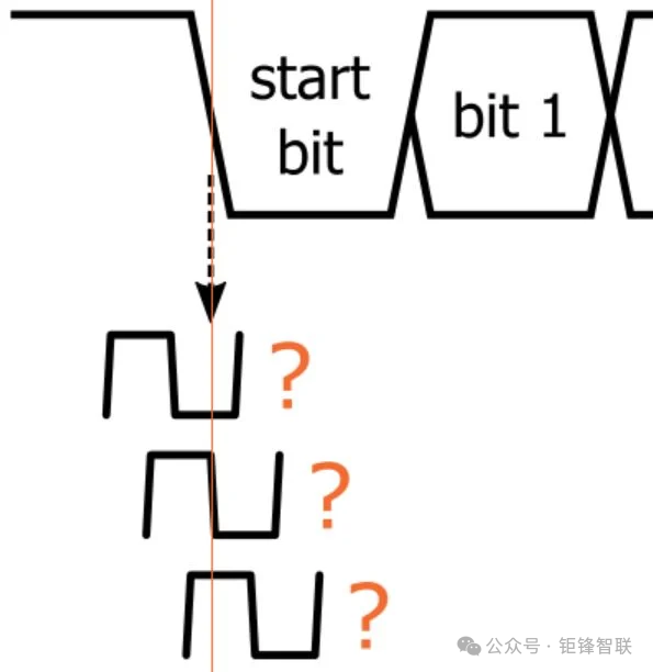
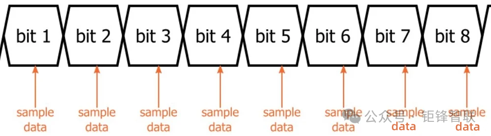
Without some form of clock mechanism, standard digital data is meaningless. The following diagram illustrates why:
Typical data signals are voltage transitions between logic low and logic high. Only when the receiver knows when to sample the signal can it correctly convert these logical states into digital data. This can be achieved by using a separate clock signal. For example, the transmitter updates the data signal on each rising edge of the clock, and then the receiver samples the data on each falling edge.
However, the UART interface does not use a clock signal to synchronize Tx and Rx devices. So how does the receiver know when to sample the transmitter’s data signal?
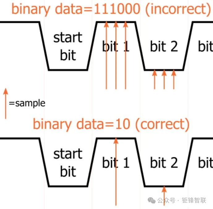
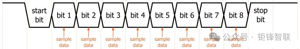
The transmitter generates a bit stream based on its clock signal, and the receiver’s goal is to sample the incoming data at the midpoint of each bit using its internal clock signal. Sampling at the midpoint of the bit is not mandatory but is optimal because sampling near the start or end of the bit can reduce the system’s robustness to differences in clock frequencies between the receiver and transmitter.
The receiving process begins with the falling edge of the start bit. This is the moment when the critical synchronization process occurs. The receiver’s internal clock is completely independent of the transmitter’s internal clock—in other words, this first falling edge could correspond to any point in the receiver’s clock cycle:
To ensure that the effective edge of the receiver’s clock occurs close to the midpoint of the bit period, the baud rate clock frequency sent to the receiver module must be much higher than the actual baud rate (8 times, 16 times, or even 32 times higher).
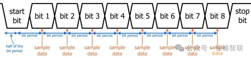
Assume a bit period corresponds to 16 receiver clock cycles. In this case, synchronization and sampling can proceed as follows:
-
The receiving process is initiated by the falling edge of the start bit;
-
The receiver waits for 8 clock cycles to establish a sampling point close to the midpoint of the bit period;
-
Then the receiver waits for another 16 clock cycles, bringing it to the midpoint of the first data bit period;
-
The first data bit is sampled and stored in the receive register, and then the module waits for another 16 clock cycles before sampling the second data bit;
-
This process repeats until all data bits are sampled and stored; after that, the rising edge of the stop bit returns the UART interface to idle state.
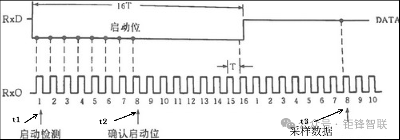
UART Serial Communication 16x Oversampling Data
The RXD front end of a standard UART has a 1-to-0 transition detector. When it continuously receives 8 ground levels on RXD, this detector considers that the RXD line has encountered a start bit and enters the receiving data state.
In the receiving state, the receiving controller samples the data bits 7, 8, and 9 and follows the majority rule to determine the final value. The fundamental purpose of this method is to enhance anti-interference and improve the reliability of data transmission. The sampling signal is always at the midpoint of each received bit, avoiding edge distortion at both ends of the data bit and preventing errors caused by the receiver’s clock frequency not being fully synchronized with the transmitter’s clock frequency.
Combined with the diagram, here’s how to ensure the sampling moment is at the midpoint of the sampled data:
-
If a low level is detected at time t1, continuous detection of this low level begins;
-
After detecting 8 clock cycles, reaching t2, if the previous 8 cycles are all low levels, it is considered that a start pulse has been detected. Otherwise, it is considered interference, and detection is restarted;
-
After detecting the start bit, count 16 sampling clock cycles to reach the midpoint of the first data bit at time t3, sampling the data and saving it;
-
Then after another 16 cycles, it reaches the midpoint of the second data bit, sampling at that moment; then after another 16 cycles, it reaches the midpoint of the third data bit, sampling at that moment… This continues until all data bits are sampled.
5. Baud Rate Error
Due to the lack of an external clock in the UART interface, reliable data communication between the transmitting and receiving devices can only occur when the internal baud rates are equal. However, “equal” is not a true engineering term—we always have to consider noise, errors, and variations.
The only relevant error is the difference between the transmitter’s baud rate and the receiver’s baud rate.
If the receiver’s baud rate matches the transmitter’s baud rate perfectly, and the first bit is sampled at the exact midpoint of the bit period, then the last data bit will also be sampled at the exact midpoint of the bit period.
If the baud rates (and bit periods) differ, each sampling point will gradually approach the bit transition. In other words, the last data bit is the most affected by the baud rate difference (for convenience, we always assume the Rx bit period is longer than the Tx bit period; if we assume the Rx bit period is shorter, the result will be the same).
5.1 Simple Assessment of Maximum Allowable Baud Rate Error
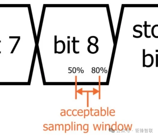
If the last bit is sampled before the transition from the last data bit to the stop bit, then the baud rate is sufficiently accurate (here, we assume the system can tolerate errors in sampling the stop bit).
However, we do not want to sample before the expected transition (1 ns or shorter), and we need some margin. A reasonable margin is generally considered to be 20%. That is, the last bit must be sampled at least 20% of the bit period before the transition from the last data bit to the stop bit.
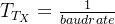
The bit period of the transmitting device is defined as follows:
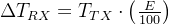
If we denote E as the absolute value of the percentage difference between the baud rate of the receiving device and the baud rate of the transmitting device, then the additional bit period time for the receiving device is:
For the first analysis, we will simplify by assuming the timing process starts at the exact midpoint of the start bit. Therefore, for an 8 data bit interface, the last data bit will deviate by 8ΔTRX:
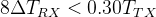
The acceptable sampling window for the last data bit mentioned earlier is from 50% (ideal value) to 80% (close to what we are willing to accept), 80% – 50% = 30% = 0.3. We can solve for the maximum allowable E as follows:
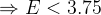
Therefore, based on this simplified analysis, as long as the difference between the baud rate of the transmitting device and the baud rate of the receiving device is less than 3.75%, UART communication with eight data bits should be reliable.
5.2 Comprehensive Analysis of Maximum Allowable Baud Rate Error
The previous section provided a rule of thumb applicable to any eight data bit UART system that can tolerate frame errors (i.e., errors indicating incorrect sampling of the stop bit). In this section, we will develop a comprehensive equation that can provide a more precise and customized estimate.
To do this, we will incorporate the following points:
-
Variable for the position of the start bit sampling
-
Variable for the number of data bits
-
Variable for the margin of the final bit sampling
-
Presence or absence of a parity bit
-
Frame error tolerance
Based on the analysis from the previous section:
Now our margin for the final bit sampling is a variable; we will use M (previously we used 20%). From the equation below, M must be input as a decimal rather than a percentage.


The number of data bits is a variable denoted by N. We will also include a variable for the parity bit (P) and stop bit (S). If you have a parity bit, P is 1; if not, it is 0. If you want to ensure the stop bit is correctly sampled, S is 1; if not, it is 0. The formula is updated as follows:

Finally, we need a variable that considers the actual sampling position of the start bit. The current form of the equation assumes 50% (i.e., the midpoint of the bit period). This is the ideal position. Any deviation from the ideal position can lead to subsequent bits being sampled closer to the transition point (thus closer to errors). We add the following term to incorporate this into the equation:

This term refers to the deviation from the ideal start bit sampling position, expressed in decimal and multiplied by the receiving device’s bit period. For example, if the start bit is sampled at 60% of the bit period, this term will be |(50% – 60%)|TRX = 0.1TRX. You cannot directly determine the exact value of this term, but if you understand the low-level functional details of UART, you can make a reasonable worst-case estimate.
Now our equation is:

Considering that the bit period of the receiving device equals the bit period of the transmitting device plus the additional time corresponding to the error percentage, our final equation is as follows:

Calculation Example
Consider the following points:
-
The margin for the final bit sampling is 30%
-
The worst-case deviation for the start bit sampling is 5%
-
8 data bits
-
No frame errors allowed
-
Using a parity bit
Plugging into the final equation:


Original Link: https://blog.csdn.net/weixin_50578108/article/details/145672518