ver0.1
Introduction
Before diving into the main topic of this article, we will introduce the subject of CPU virtualization to lay the groundwork. The purpose of the system issuing an interrupt signal is to send notifications from devices to the CPU (PE-Core). In a virtualized system, each VM runs on a vCPU, which determines that the handling of interrupt signals in virtualized and non-virtualized environments will differ. How does a CPU, after being processed by a Hypervisor for virtualization, receive and respond to interrupt signals? Does the interrupt signal require special processing before being delivered to the vCPU? These questions will be addressed in the discussion of the interrupt virtualization architecture and working principles in this article.
Similarly, before proceeding, it is recommended that readers familiarize themselves with the knowledge system introduced in previous articles:
(0)[V-00] Introduction to Virtualization – Conceptual Overview
(1)[V-02] Basics of Virtualization – CPU Architecture (Based on AArch64)
(2)[V-05] Basics of Virtualization – Exception Model (AArch64)
(3)[A-25] ARMv8/v9-GIC System Architecture (Hardware Foundation of Interrupts)
(4)[A-26] ARMv8/v9-GIC Interrupt Types
(5)[A-27] ARMv8/v9-GIC Core Components (Basic Components of Interrupt Programming)
(6)[A-28] ARMv8/v9-GIC Interrupt Signal Routing Mechanism and Strategy
(7)[A-29] ARMv8/v9-GIC – Security Architecture Design of the Interrupt Subsystem (Security/FIQ/IRQ)
(8)[A-30] ARMv8/v9-GIC – Interrupt Handling (Interrupt State Machine/Interrupt Lifecycle)
(9)[A-31] ARMv8/v9-GIC – Interrupt Handling (Interrupt Priority/Interrupt Preemption/Interrupt Nesting)
(10)[A-32] ARMv8/v9-GIC – Architecture and Working Mechanism of LPI Type Interrupts
(11)[V-10] ARMv8/v9-CPU Virtualization – Introduction to CPU Virtualization Architecture (vCPU/vPE)
Main Text
1.1 System Architecture of Virtualized Interrupts
1.1.1 Background
To do a good job, one must first sharpen their tools. The destination of the interrupt signal is the CPU (PE-Core). In a non-virtualized software architecture environment, the routing and distribution of this interrupt signal through the GIC core components simply needs to find the corresponding PE-Core, as shown in Figure 1-1.
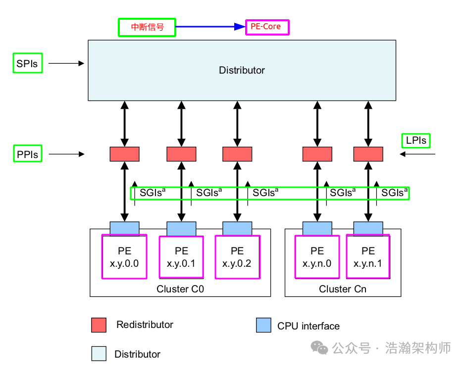
Figure 1-1 GIC System Architecture
The green signals represent physical interrupts, and their destination is the purple PE-Core. After routing and distribution through the GIC and priority comparison, these signals are directly delivered to the current PE-Core via the GIC-CPU-Interfaces. At this point, regardless of the execution level (Exception Level) and security state (Security State) of the PE-Core, it will stop executing the current instruction flow according to the established configuration policy, save the context, and jump to the interrupt handler to execute. Although this process is logically clear for physical interrupts, those who have read our previous articles on interrupts should know that it is quite complex in reality. Just configuring the routing of various signals requires significant effort and involves many registers, as shown in Figure 1-2.
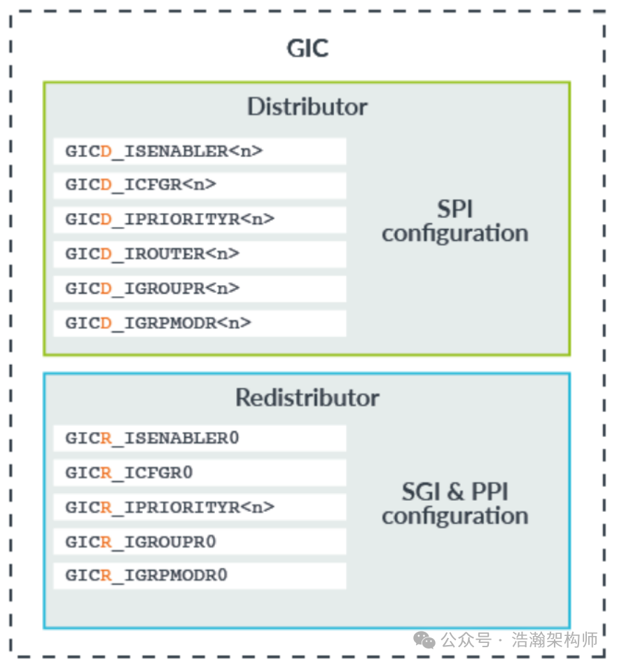
Figure 1-2 Core Registers of GIC
With the support of the above registers, a physical interrupt signal can successfully reach the PE-Core at runtime. For the GIC, the final stop in this process is the GIC-CPU-Interface.
Based on the above background, when we switch to a virtualized scenario, the situation becomes more complex. From a system perspective, all devices are isolated by the Hypervisor, but most of the business layer code resides within the VM, as shown in Figure 1-3.
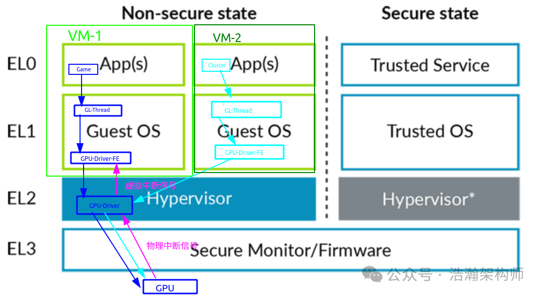
Figure 1-3 Scenario of Concurrent Access to GPU by VMs
In the above example, we illustrate a scenario of concurrent access to hardware devices, where two VM applications require GPU rendering data. When the GPU completes a task issued by one VM, it will notify the CPU by sending an interrupt signal to the GIC, allowing the CPU to relay the task completion status to the application of that VM through the interrupt handler. How can the interrupt signal sent by the GPU ensure correct delivery to the corresponding VM? This is where the Hypervisor comes into play. It is easy to understand that the Hypervisor isolates hardware devices, so it must manage the hardware, including the message link between applications and hardware devices.
1.1.2 System Architecture of Virtualized Interrupts (Virtual and Physical CPU Interfaces)
The ball is once again in the Hypervisor’s court. After intercepting the physical interrupt signal from the device through the core components of the GIC architecture, it must consider how to deliver this signal to the VM. The key information here is that, as we learned in the previous article, VMs run on vCPUs, so the physical interrupt signal that the Hypervisor forwards must also be sent to the vCPU, as shown in Figure 1-4.
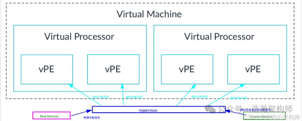
Figure 1-4 Hypervisor Intercepts and Sends Virtual Interrupt Signals
Note that the Emulated Device in the lower left corner is obscured by a watermark, indicating that the Hypervisor can not only forward interrupt signals sent by real physical devices but also those sent by purely software-emulated devices. To improve the forwarding efficiency of the Hypervisor, the GIC has designed new hardware units to assist in the delivery of virtual interrupt signals, as shown in Figure 1-5.
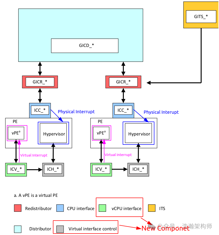
Figure 1-5 GIC Architecture for Assisting Virtual Interrupt Processing
Compared to Figure 1-1, these two new GIC components are the vCPU interface and virtual interface control. Like other GIC components, they also require programming of their internal registers to function. We can simplify the above diagram as shown in Figure 1-6.
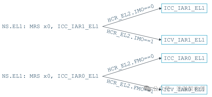
Figure 1-6 GIC Architecture for Assisting Virtual Interrupt Processing
Let’s take a look at the introduction in the manual:
The CPU interface registers are split into three groups:
• ICC: Physical CPU interface registers
• ICH: Virtualization control registers
• ICV: Virtual CPU interface registers
Physical CPU interface registers
These registers have names with the format ICC_*_ELx.
The hypervisor executing at EL2 uses the regular ICC_*_ELx registers to handle physical interrupts.
Virtualization control registers
These registers have names with the format ICH_*_EL2.
The hypervisor has access to additional registers to control the virtualization features provided by the architecture. These features are as follows:
• Enabling and disabling the virtual CPU interface.
• Accessing virtual register state to enable context switching.
• Configuring maintenance interrupts.
• Controlling virtual interrupts for the currently scheduled vPE.
Virtual CPU interface registers
These registers have names with the format ICV_*_EL1.
Software executing in a virtualized environment uses the ICV_*_EL1 registers to handle virtual interrupts. These registers have the same format and function as the corresponding ICC_*_EL1 registers.
The ICV and ICC registers have the same instruction encodings. At EL2 and EL3, the ICC registers are always accessed. At EL1, the routing bits in HCR_EL2 determine whether the ICC or the ICV registers are accessed.
Combining Figures 1-5 and 1-6, we can explain the GIC Virtual and Physical CPU interfaces:
(1) GIC can directly distribute physical interrupt signals to PE-Core through Physical CPU interfaces.
(2) GIC can send virtual interrupt signals to vPE under the intervention of Hypervisor software through the Virtual CPU Interface.
(3) GIC Virtual CPU interfaces also need to be configured at runtime to work.
• The ICV_*_EL1 registers are relatively easy to understand; their format and working principles are similar to those of ICC_*_EL1, and they can even be interchangeable under certain configurations, as shown in Figure 1-7.
Figure 1-7 Example of ICC or ICV Register Selection
The advantage of this design is mainly its ease of portability; some related code for interrupt handling in the VM kernel can be used directly without modification.
• The ICH_*_EL2 registers are primarily used to control key features of virtual interrupts. To fully understand this part, in addition to the content introduced in the previous sections of this article, it is strongly recommended to read the previous articles on CPU virtualization; otherwise, it will be quite challenging to grasp without any foundational knowledge. Here is an example (ICH_LR<n>_EL2, Interrupt Controller List Registers, n = 0 – 15), as shown in Figure 1-8:

Figure 1-8 GIC-CH_LR<n>_EL2
Let’s look at the description in the manual:
The state of the interrupt:
State — Meaning
0b00 — Invalid (Inactive).
0b01 — Pending
0b10 — Active.
0b11 — Pending and active.
The GIC updates these state bits as virtual interrupts proceed through the interrupt life cycle. Entries in the invalid state are ignored, except for the purpose of generating virtual maintenance interrupts.
For hardware interrupts, the pending and active state is held in the physical Distributor rather than the virtual CPU interface. A hypervisor must only use the pending and active state for software-originated interrupts, which are typically associated with virtual devices or SGIs.
This register stores the state and other information of virtual interrupts, and the description indicates that virtual interrupts only have two valid states (pending and active). The manual clearly states that for interrupts requiring Pending, they should not be pending during the virtualization processing phase. Those who have read the previous articles on physical interrupts should find this point about virtual interrupt states relatively easy to understand. However, one point that must be understood is that if the vPE is preempted while processing this virtual interrupt, the state of the associated register CH_LR<n>_EL2 needs to be saved during the vCPU thread context switch, and when the vCPU resumes execution, the content of this register also needs to be restored, as referenced in the manual’s description.
As described in Managing virtual interrupts, virtual interrupts are managed using the List registers. The state of these registers is specific to the current vPE. Therefore, these registers must be saved and restored on context switches.
In fact, the Hypervisor can throw interrupts to the vCPU in a purely simulated manner without relying on the GIC, but that method is too inefficient (handling an interrupt in a VM involves a lot of context switching into EL2). We will not focus on that discussion; interested readers can refer to the manual.
1.2 Software Architecture of Virtual Interrupts
1.2.1 Interrupt Vector Table (Exception Vector Table)
From previous articles, we know that interrupts in the ARM exception system belong to asynchronous exception types. In the ARM architecture, the software architecture of interrupts is also part of the exception software architecture:
When an exception occurs, the processor must execute handler code that corresponds to the exception. The location in memory where the handler is stored is called the exception vector. In the ARM architecture, exception vectors are stored in a table, called the exception vector table.
Each Exception level has its own vector table, that is, there is one for each of EL3, EL2, and EL1. The table contains instructions to be executed, rather than a set of addresses. These would normally be branch instructions that direct the core to the full exception handler.
The exception vector table for EL1, for example, holds instructions for handling all types of exceptions that can occur at EL1. Vectors for individual exceptions are at fixed offsets from the beginning of the table. The virtual address of each table base is set by the Vector Base Address Registers: VBAR_EL3, VBAR_EL2, and VBAR_EL1.
Combining the description from the manual, let’s recognize the exception vector table, as shown in Figure 1-9:
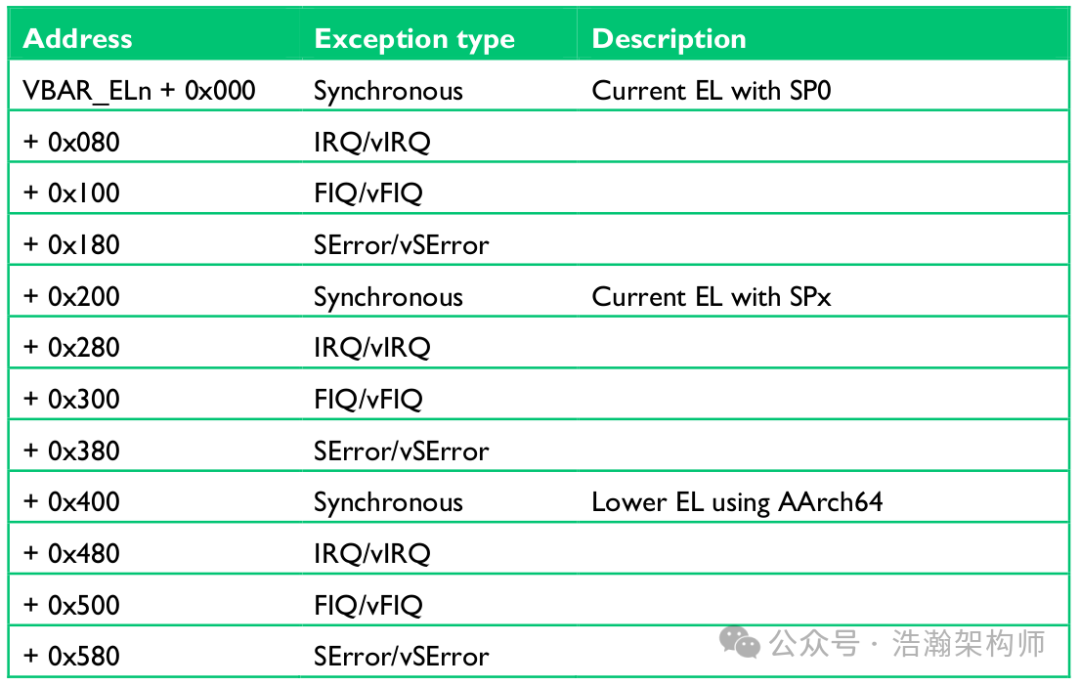
Figure 1-9 Exception Vector Table in ARM Architecture
This section will not be discussed in detail; the selected description from the manual is clear. Here we will briefly summarize the working principles of the interrupt vector table:
(1) Interrupt Trigger Phase: When a peripheral or software generates an interrupt signal, this signal is sent to the ARM processor’s interrupt controller (such as GIC).
(2) Interrupt Identification Phase: After receiving the interrupt signal, the interrupt controller identifies and classifies the interrupt, determining its type. This mainly involves identifying the grouping information and exception type (IRQ/FIQ/vFIQ/vIRQ) based on system configuration; in actual production projects, this will not be configured so complexly.
(3) Vector Table Lookup Phase: The processor finds the corresponding address from the vector table based on the type of interrupt. For example, if the CPU is currently executing Kernel code and an IRQ interrupt arrives, the address VBAR_EL1+0x280 will be selected (note that the specific configuration and implementation of the software and hardware system must be considered).
(4) Jump Execution Phase: The processor sets the program counter (PC) to the address read from the vector table, thus jumping to the entry of the corresponding interrupt handler and starting to execute the interrupt handling code. In the example from (3), the jump will occur as shown in Figure 1-10:
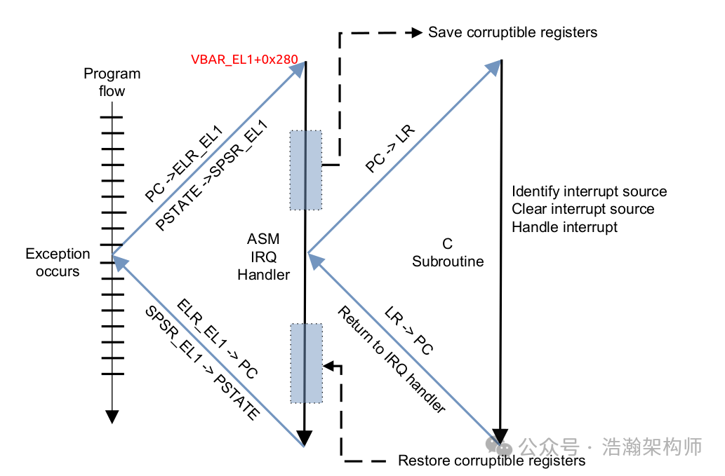
Figure 1-10 ARM Interrupt Exception Handling
(4) Interrupt Return Phase: After the interrupt handler has finished executing, it will restore the processor’s state to what it was before the interrupt occurred using specific instructions (such as the RFE instruction) and continue executing the interrupted program, which is the lower part of Figure 1-10.
1.2.2 Software Architecture of Virtual Interrupts
With the above foundation, the software architecture of virtual interrupts becomes clearer, as shown in Figure 1-11:
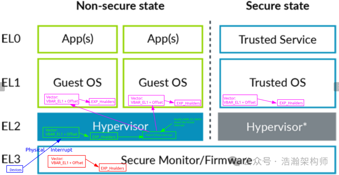
Figure 1-11 ARM Virtual Interrupt Software Architecture
After the groundwork laid in the previous sections, understanding the above software architecture diagram should not be difficult. The only point to emphasize is that when multiple VMs are working simultaneously, the Hypervisor must first update the base address in the corresponding VAVR_EL1 register before injecting interrupts into the respective VM’s PE-Core.
Next, let’s go through a simple example from the manual to connect the virtual interrupt processing flow and deepen our understanding of the interrupt virtualization architecture, as shown in Figure 1-12:
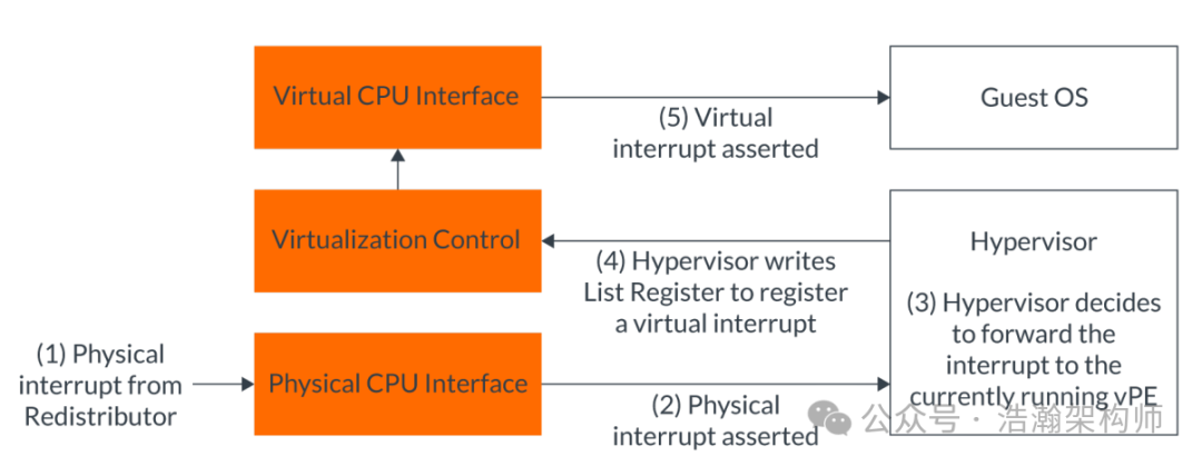
Figure 1-12 Example of a Physical Interrupt Being Forwarded to a vPE
Combining Figure 1-12, I summarize the following:
(1) First, a physical interrupt is injected into a PE-Core through the GIC’s Redistributor and CPU-Interface (note that different interrupt types may have different paths). Depending on the current execution state or configuration of the PE-Core, physical interrupts from peripherals are generally intercepted and processed by the Hypervisor as IRQ types.
(2) After the Hypervisor receives the physical interrupt signal, it needs to identify the vPE in the Running state of the target VM to inject this interrupt. The process of selecting the vPE varies among Hypervisor vendors, but generally falls into two categories: static allocation, which is simple but not well-balanced, and dynamic allocation, which aims to balance the load across vCPUs but involves complex algorithms that require rigorous validation and testing. After finding the vPE, the relevant virtual interrupt information is updated in the Virtual CPU Interfaces and virtual control registers. At this point, the Virtual CPU Interface will perform checks on the virtual interrupt information injected by the Hypervisor, such as MASK and Priority. If the checks pass, it will directly send the interrupt vIRQ/vFIQ to the vPE, which is essentially sending a physical interrupt to the current PE-Core, but this time the response is from the current VM’s vPE thread.
(3) The vPE thread continues execution, but it will interrupt the current EL0/EL1 execution flow, save the context, and jump to the address of the interrupt vector table at VAVR_EL1+Offset to begin execution.
(4) After the Guest OS processes the interrupt, it performs cleanup work, updates the relevant registers, and returns through multiple layers.
Note: This process involves the scheduling of the vPE thread, so attention must be paid to saving and restoring the vPE-related context at the EL2 level; we will not elaborate on this here.
Conclusion
We will temporarily conclude our discussion on the interrupt virtualization architecture here. This article only covers the virtualization architecture of traditional interrupts; the latest GIC versions also support directly delivering interrupt signals to vPEs. This method is more efficient, but it does not mean that the traditional interrupt virtualization architecture will be abandoned. Instead, depending on the specific system architecture design and the implementation of the Hypervisor, both methods work closely together to push the efficiency of interrupt virtualization to the limit, providing users with a better experience. There are many interesting points regarding interrupt virtualization that we have not covered due to space limitations; we will stop here for today. Please feel free to like, follow, and share. Thank you all, and see you in the next article.
Reference
[00] <Armv8-A-virtualization.pdf>
[01] <DEN0024A_v8_architecture_PG.pdf>
[02] <learn_the_architecture_aarch64_exception_model.pdf>
[03] <corelink_gic_720ae_generic_interrupt_controller_trm.pdf>
[04] <arm_generic_interrupt_controller_v3_and_v4_virtualization_guide.pdf>
[05] <learn_the_architecture_generic_interrupt_controller_v3_and_v4_lpis.pdf>
[06] <80-ARM-GIC-wx0005_Arm-gicv3_v4学习这一篇就够了.pdf>
[07] <80-ARM-GIC-wx0003_ARM架构Generic-Interrupt-Controller-GIC之Distributor和CPU-interface.pdf>
[08] <80-ARM-GIC-HK0001-一文搞懂GICv3中断控制器的工作原理.pdf>
[09] <80-ARM-GIC-wx0001_ARM-gicv3_gicv4的总结-基础篇.pdf>
[10] <80-ARM-INT-yk0001_万字长文玩转中断:从硬件看中断之GIC.pdf>
[11] <learn_the_architecture_generic_timer.pdf>
[12] <learn_the_architecture_trustzone_for_aarch64.pdf>
[13] <learn_the_architecture_realm_management_extension.pdf>
[14] <locality-specific_peripheral_interrupts_arm_generic_interrupt_controller.pdf>
[15] <80-Virt-ARCN-OVW-I0001_ACRN_High-Level_Design_Overview.pdf>
[16] <80-Virt-ACRN-vCPU-I0001_CPU_Virtualization.pdf>
[17] <80-Virt-ACRN-INT-I0001_Physical_Interrupt_High-Level_Design.pdf>
[18] <SysReg_xml_A_profile-2024-03.pdf>
Glossary
GIC – Generic Interrupt Controller
SCMI – System Control and Management Interface (SCMI)
ACPI – Advanced Configuration and Power Interface (ACPI)
PSCI – Power State Coordination Interface (PSCI)
UEFI – Unified Extensible Firmware Interface (UEFI)
UART – Universal Asynchronous Receiver/Transmitter
SPI – Shared Peripheral Interrupt
PPI – Private Peripheral Interrupt
SGI – Software Generated Interrupts
MPAM – Memory System Resource Partitioning and Monitoring
LPI – Locality-specific Peripheral Interrupt (LPI)
PE – Processing Element
MSI – message-signaled interrupts (MSI)
IAR – Interrupt Acknowledge Registers
EOIR – End of Interrupt Registers
IRM – Interrupt Routing Mode
ITS – Interrupt Translation Service
ITT – Interrupt Translation Tables
vPE – virtual processing element
IPI – inter-processor interrupts
IRI – Interrupt Routing Infrastructure
EOI – End of interrupt
REE – Rich Execution Environment
TEE – Trusted Execution Environment
NMI – Non – Maskable Interrupts
RAZ – Read-As-Zero
WI – Writes Ignored
vPE – virtual Processing Element
vCPU – virtual CPU
VM – virtual machine