ver0.2
Introduction
In the previous article, we introduced the working principle of the Generic Timer, analyzing the System Counter and the set of Timers on each PE-Core. Initially, we planned to introduce the architecture and workflow of the Generic Timer in a virtualization scenario as well, but upon completion, we found the length was too extensive, so we divided it into two articles. In this article, we will first introduce the virtualization architecture of the Generic Timer, and then discuss the workflow of the Generic Timer in a virtualization scenario, aiming to help everyone re-understand the Generic Timer from the perspective of virtualization frameworks. Before reading this article, we hope everyone will read the preceding articles as a foundation, especially those related to virtualization technology:
(1)[V-00] Introduction to Virtualization – Conceptual Part
(2)[A-38] ARMv8/v9 Generic Timer System Architecture
(3)[V-05] Basics of Virtualization – Exception Model (AArch64)
(4) ARM Interrupt Subsystem
(5)[V-02] Basics of Virtualization – CPU Architecture (Based on AArch64)
(6)[V-04] Basics of Virtualization – Register Set (Based on AArch64)
(7)[A-17] ARMv8/ARMv9 Memory – Memory Barrier Mechanism (Observer & Barrier)
(8)[A-15] ARMv8/ARMv9 Memory – Weakly Ordered Memory Model (Efficiency First)
(9)[A-39] ARMv8/v9 Generic Timer Working Principle
(10)[V-08][Device Virtualization] – Software Virtualization Technology vs Hardware Virtualization Technology
(11)[V-10] ARMv8/v9 CPU Virtualization – Introduction to CPU Virtualization Architecture (vCPU/vPE)
Main Content
Before writing this article, we consulted a lot of materials, including those from ARM, QCOM, MTK, and some papers related to Timers. The conclusion is: at the software level, you can design it however you want; the ARM generic timer system supports it.
1.1 Background of Timer Virtualization
1.1.1 Time Subsystem Requirements
Any operating system’s requirements for time can generally be summarized into three categories:
(1) Real time (RTC, wall clock time), year, month, day, hour, minute, second, all local contexts that need to use real time. Whether recording surveillance video in the background or synchronizing with the cloud (as shown in Figure 1-1), this is the time that needs to be accessed and manipulated.
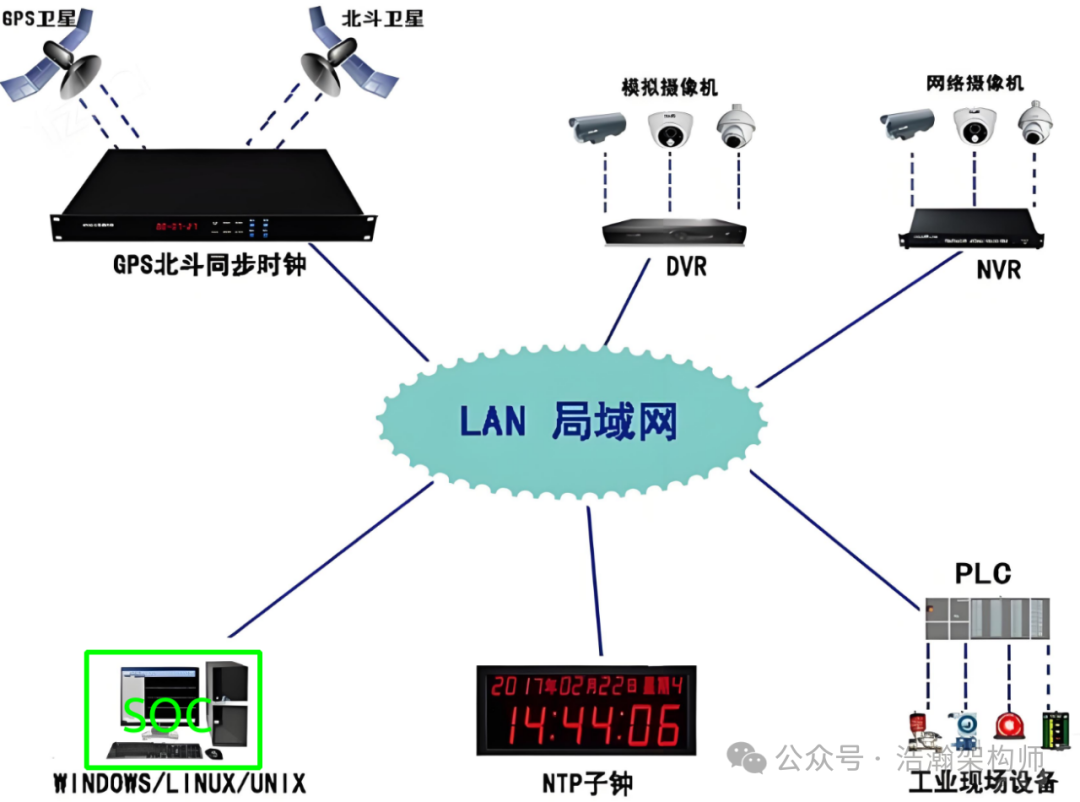
Figure 1-1 NTP Synchronization Diagram
(2) Timed events (Timers), which set up a mechanism similar to an alarm clock to execute a task when the time comes. This task can be one-time, such as setting an ALARM clock, or periodic, such as the Scheduler tick used by various systems (as shown in Figure 1-2).
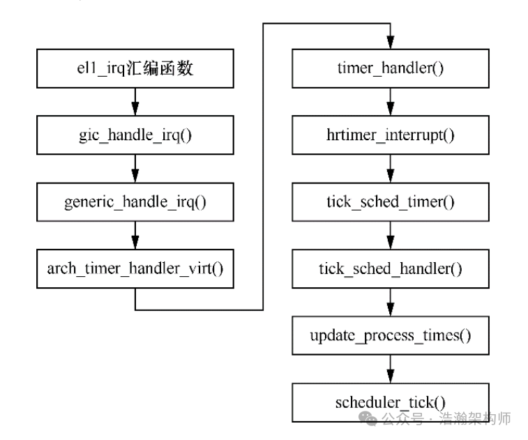
Figure 1-2 Linux Clock Interrupt Response Process
(3) Recorded time (System Counter), which is the time elapsed since the system started running. The software system needs a common reference, and the business code running on each PE-Core needs to align with this time (as shown in Figure 1-3) to work more accurately.
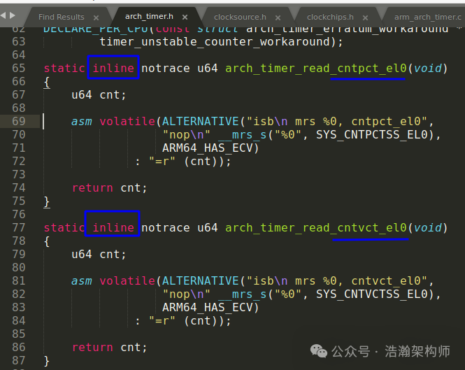
Figure 1-3 Code Snippet for Accessing System Counter in Linux
1.1.2 TIMER VIRTUALIZATION
In a virtualization scenario, the situation becomes complex. Compared to a single system, the most significant change is that time synchronization is also required between VMs, between VMs and the Host, and between VMs and the Hypervisor, thus imposing higher requirements on Timer virtualization. Let’s look at the description in the literature:
The timer is essential for any operating system: without it, there could be no process scheduling in the context of preemptive scheduling. Operating systems also use a timer for periodic tasks, either as a functionality offered to user space processes or for internal purposes. It is necessary for a virtual machine to have access to a virtualized timer in order for the guest operating system to function properly.
The host operating system needs to use a timer exclusively; it is not desirable for a virtual machine to slow down the host.
Timer interrupts are extremely time-sensitive. Timer interrupts come at regular intervals (the FreeBSD kernel configures the timer to fire once every 1 millisecond) and because they are so frequent, it is extremely undesirable to spend too much time servicing the interrupt. That time can be used instead to execute other tasks. The same is true for the virtualized timer: the less time the hypervisor spends emulating a timer, the more CPU time a virtual machine has at its disposal before the next interrupt.
Through the analysis of requirements and the introduction of our previous articles, ARM’s Generic Timer “basically” meets these needs. Below is an abstraction of these requirements, layered design embedded into the software system. From the perspective of the software system, all nodes on the SoC are devices, and the core components of the Generic Timer are also devices. The working model of the device consists of two aspects: upstream and downstream. Let’s look at a scenario described in the literature:
Fig. 1-4 shows the steps the FreeBSD kernel executes when handling a timer interrupt. To get the interrupt number, the Interrupt Acknowledge Register (IAR) is read. The interrupt number is the number programmed in the List Register. This changes the interrupt state from pending to active. The kernel disables the timer by writing to the CNTP CTL EL0 register, which causes a trap to the hypervisor where the hypervisor does in-kernel emulation. As a result of the write, the hypervisor disables all pending timer alarms for the guest. The guest programs the timer for the next alarm, and we save this value. We don’t program any alarms to inject an interrupt because the timer is still disabled.
Only after the guest enables the timer with another write to CNTP CTL EL0 do we trap to the hypervisor and program an alarm at the time specified by the guest by using the FreeBSD’s callout API. To end the handling of this interrupt, the kernel writes to the End Of Interrupt Register (EOIR), which marks the interrupt as inactive in the List Register. The List Register that held the interrupt is now available to be used for injecting another interrupt.
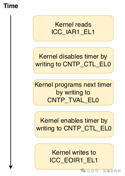
Figure 1-4 Timer Usage
Based on the literature description, we summarize the content related to Timer virtualization as follows:
(1) Upstream refers to the timer interrupt, which notifies the software that it needs to perform a task when the time is up. In the virtualization architecture, this software refers to software at various levels, mainly EL2/EL1.
(2) Downstream mainly controls the behavior of the clock, such as turning off the clock or setting the next alarm time. At this point, the Hypervisor needs to intervene. For example, if VM1 wants to turn off the clock, this is just VM1’s intention; whether it can be turned off depends on the intentions of other VMs and the design of the Hypervisor itself.
(3) Why is it “basically” satisfied? From the perspective of hardware configuration and design, the Generic Timer should be fine, even if the RTC not covered by the Generic Timer, the SoC manufacturer must ensure it is fine to sell the chip. Even so, it is still “basic” because to fully meet the requirements, we need to look at the implementation of the Timer virtualization architecture, which tests the strength of the Hypervisor vendor (in our currently mass-produced project, two VMs often have a difference of 2s to 3s, and the log timestamps are inaccurate; how to describe the mood? Painful but not happy).
1.2 Generic Timer Virtualization Architecture
In the previous section, we briefly reviewed the Timer subsystem from the perspective of requirements and clarified the background of Generic Timer virtualization. In this section, we will outline the Timer virtualization architecture.
1.2.1 Single System Architecture
First, let’s look at the architecture of a single system (Native OS), as shown in Figure 1-5:
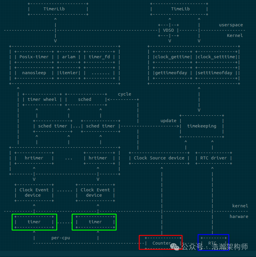
Figure 1-5 Linux Timer Architecture
The purpose of the above diagram is to help everyone establish a sense of the combination of Timer hardware and software in their minds. We will not discuss it in detail here, but will summarize it based on the block diagram:
(1) At the hardware level, the most concerned core devices for the Kernel’s Timer subsystem are the Hardware RTC, System Counter, and Timers. This can be corroborated with the system architecture of the Generic Timer introduced earlier.
(2) At the software level, the Kernel first abstracts these three types of devices: Clock Event Devices, Clock Source Devices, and timekeeping (RTC Driver). After abstraction, it facilitates the adaptation of physical devices from the BSP level. For example, Timekeeping, as the core of Linux time maintenance, is provided by the counter for continuous high-precision timing, while the RTC or network NTP provides a real-world time reference to maintain the accuracy and reliability of various system times. Here we excerpt part of the content from the Kernel documentation to help deepen understanding:
To provide timekeeping for your platform, the clock source provides the basic timeline, whereas clock events shoot interrupts on certain points on this timeline, providing facilities such as high-resolution timers. sched_clock() is used for scheduling and timestamping, and delay timers provide an accurate delay source using hardware counters.
Clock sources
The purpose of the clock source is to provide a timeline for the system that tells you where you are in time. For example, issuing the command ‘date’ on a Linux system will eventually read the clock source to determine exactly what time it is.
Clock events
Clock events are the conceptual reverse of clock sources: they take a desired time specification value and calculate the values to poke into hardware timer registers.
(3) Relying on the Kernel’s abstraction of Timer devices, the Kernel begins to strengthen and encapsulate a layer of intermediate management data structures to facilitate linking time-related business code and controlling devices. For example, in the high-precision version, each Clock event device creates a local high-precision timer hrtimer management structure. hrtimer is event-driven and manages various types of software timing tasks on that CPU through a red-black tree. Each time an overdue task is executed, it selects the overdue task with the nearest overdue time to set the next overdue value. We also excerpt part of the kernel help documentation to deepen everyone’s understanding:
hrtimers – rounding of timer values
the hrtimer code will round timer events to lower-resolution clocks because it has to. Otherwise it will do no artificial rounding at all.
one question is, what resolution value should be returned to the user by the clock_getres() interface. This will return whatever real resolution a given clock has – be it low-res, high-res, or artificially-low-res.
hrtimers – testing and verification
We used the high-resolution clock subsystem ontop of hrtimers to verify the hrtimer implementation details in praxis, and we also ran the posix timer tests in order to ensure specification compliance. We also ran tests on low-resolution clocks.
The hrtimer patch converts the following kernel functionality to use hrtimers:
• nanosleep
• timers
• posix-timers
The conversion of nanosleep and posix-timers enabled the unification of nanosleep and clock_nanosleep.
(4) With these intermediate Timer management data structures, further encapsulation is done based on the usage scenario. For example, various types and precision software timers are encapsulated based on hrtimer, and to facilitate kernel usage, a heartbeat timer (sched_timer) is defined to drive task scheduling, load calculation, and other low-precision timers based on timer wheel. To facilitate user space usage, interfaces such as posix-timer, alarm, timer_fd, nanosleep, and itimer are defined. Timekeeping not only provides rich time acquisition interfaces for kernel modules but also encapsulates many system calls for user space use, particularly bypassing system calls through VDSO technology to efficiently obtain system time. Additionally, the task scheduling module (sched), printk/ftrace timestamps, etc., also rely on the counter to provide high-precision timing.
The reason for this slight transition is: if one does not understand the Timer architecture of a single system, jumping directly to the virtualization architecture would be too steep. It is still necessary to lay the groundwork to understand the Timer architecture of a single system before understanding the virtualization system, which makes it easier. We will stop here for the introduction of the Timer architecture of a single system. Interested friends can refer to the references in our appendix or directly read the kernel code and help documentation (when in doubt, ask the code; when in doubt, look at the documentation, haha).
1.2.2 Virtualization Architecture
With the above foundation, introducing the virtualization architecture of the Generic Timer should be relatively easier:
(1) Business sorting at the virtualization level can actually refer to the requirements of a single system and make a comparison:
• First, the abstraction of Timer-related devices, which is related to the specific virtualization architecture. For example, the management entity of these Timer devices can be placed in the Hypervisor or bypassed through the Hypervisor to a specific Host VM.
• Even in a virtualized system, the majority of Timer device usage still lies within each VM. Taking VMs as an example, the current scheduling algorithms at the virtualization level are far less complex than those within the VM, and the dependency on Timers is still high within the VM. Fortunately, due to the architecture design of front-end and back-end drivers, in most scenarios, the virtual Timer devices within the VM can be decoupled from the real physical Timer devices, meaning that the Timer subsystem within the VM does not need to undergo large-scale customization due to virtualization.
• With the VM decoupled, the pressure shifts to the Hypervisor: it must adapt to the physical Timer devices well; arbitrate the control operations of each VM on Timer devices; correctly distribute physical Timer interrupts and inject Timer virtual interrupts back to the VM’s vCPU (the ARM interrupt subsystem virtualization is relatively good, especially with the high version of GIC being quite convenient); finally, it must also manage its own business dependencies on the Timer subsystem and encapsulate it layer by layer to facilitate the use of various software modules within the Hypervisor, such as the Scheduler module.
(2) The Generic Timer virtualization system lacks a unified and generalized architectural scheme due to the fragmentation of Hypervisor solutions. We consulted many documents and materials but found no consistent architecture scheme. MTK and Qualcomm differ, and Qualcomm’s new and old platforms are also different; different virtualization schemes vary (Q+A vs L+A). Some descriptions and diagrams in the literature are quite rough, to the extent that we lack a ready-made architecture diagram (smiling with a hint of fatigue).
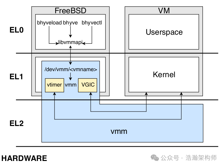
Figure 1-6 bhyvearm64 architecture
Based on the difficult situation above, we decided to personally draw a Timer virtualization architecture diagram. (After all, facing a difficult situation, Li Yunlong once said: If I had that condition, how exciting it would be to hold a machine gun and shoot, roll, roll, roll, and find a way myself.) We absorbed various literature and some open-source Hypervisor code to provide our understanding of the Timer virtualization architecture, as shown in Figure 1-7:
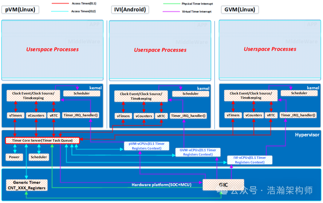
Figure 1-7 Generic Timer Virtualization Architecture
Combining Figure 1-7, we analyze the virtualization architecture of the Generic Timer:
(1) First, all processes in Userspace are unaware users of the Timer system, so they do not need to care about any specific behaviors of Timer virtualization.
(2) The VM at the EL1 level accesses the physical Timer through the virtual Generic Timer device front-end driver.
(3) The Timer Core Server at the EL2 level needs to intercept and maintain the context of all VMs’ operations on the physical Generic Timer, maintain the VM Timer Task queue, and complete the configuration actions for the Generic-related registers.
(4) When the Generic Timer timeout meets the conditions for triggering a Timer interrupt, the GIC sends the Timer’s PPI interrupt to the physical CPU’s GIC-CPU-IF (IRQ). The Hypervisor needs to intercept these PPI interrupts and process them. The Hypervisor’s own timing tasks can be handled directly, such as scheduling the vCPU threads. If it is a timing task for a specific VM, it needs to inject the virtual Timer’s virtual interrupt back to the GIC and inject the corresponding virtual interrupt into the appropriate vCPU thread through the GIC-CPU-IF (vIRQ).
(5) At this point, the Timer subsystem at the EL1 level receives the virtual interrupt information sent by the Generic Timer and responds accordingly to the intent of the interrupt, such as performing thread scheduling actions at the EL1 level.
The above is the general workflow of the Generic Timer virtualization architecture. The implementation schemes of various vendors are actually quite similar, but there are still some points that need to be particularly emphasized:
(1) The Timer core server module does not necessarily have to be implemented at EL2; it can also be in the Host-VM’s EL1 or even EL0, depending on the specific implementation scheme.
(2) The architecture diagram above ignores the RTC control link. On one hand, the RTC implementation scheme depends on the specific SoC implementation scheme; on the other hand, RTC control is also related to the control of other Timer bus devices, such as the PLL subsystem, which deviates from the main line of content we are introducing today, so we will not elaborate on it here.
1.2.3 Typical Virtualization Architecture Working Scenario
In the previous section, we introduced the typical architecture of the Generic Timer and outlined the workflow of the Timer in the virtualization architecture. In this section, we will provide a specific example to help everyone understand the virtualization of the Generic Timer, which is to look at the above architecture in a specific scenario. First, let’s look at the introduction of some basic concepts of VMs in the manual:
The different states of a virtual machine.
• Paused: All activity in the virtual machine has stopped to a level from which it is possible to save the context of the virtual machine. The saved context can be restored at a later time, so that the virtual machine can resume execution to a running state.
• Running: The virtual machine is assigned to a physical machine and can respond to user commands. When a virtual machine is running, virtual Processing Elements (PEs) can be in one of the two following states.
o Scheduled in: A virtual PE is scheduled in, or running, when it is executing guest code because it is currently assigned to physical PE.
o Scheduled out: A virtual PE is scheduled out if it is not currently assigned to any physical PE, and therefore is not executing code.
To describe the various views of the passage of time that can be observed by a virtual machine, or a hypervisor, this document uses the following terminology.
• Physical Time: Time that always progresses, regardless of whether the virtual machine is running or paused. For any virtual machine, physical time is the amount of time that machine has been in existence.
• Live Physical Time: Time that progresses whenever a virtual machine is running on a physical machine, regardless of whether or not it has any virtual PE scheduled in. This time does not progress while the virtual machine is paused.
• Virtual Time: Time that progresses only when a virtual PE in the virtual machine is scheduled in. Virtual time can be tracked individually per virtual PE, or for a whole machine. In the latter case, virtual time tracks the time that any virtual PE in the machine is scheduled in. Tracking virtual time is not covered in this document.
• Stolen Time: Time during which a virtual PE is scheduled out. Stolen time does not account for any time during which:
o the virtual machine voluntarily chooses not to execute instructions on the virtual PE, or
o the virtual machine is paused.
We summarize the descriptions in the manual:
(1) After reading our article on CPU virtualization architecture, understanding the Paused and Running states of VMs is not difficult. This is because all Guest OS code of the VMs actually needs to execute with the help of the vCPU’s Context, and the vCPU, from the perspective of the Hypervisor, is a thread, which inherently has Paused and Running states.
(2) The concept of time becomes complex after virtualization, giving rise to multiple time concepts, among which the concept of Stolen Time is particularly interesting. Here we explain that under normal circumstances, the VM does not perceive that it is running in a virtual environment; it believes it has the entire SoC world. However, in reality, all operations of the VM are completed under the supervision of the Hypervisor, and the Hypervisor, to balance the allocation of system resources among various VMs, sometimes interrupts the execution flow of the VM’s vCPU to allow other VMs to execute code, which is the aforementioned Paused state or Scheduled Out state. However, this paused execution state is imperceptible to the VM. This can lead to a situation where the actual execution time of the VM does not match the perceived execution time of the VM. In a relatively long cycle, the actual execution time of the VM is shorter, and this shorter time is the Stolen Time.
Based on the above background, we design a model: a virtualized system has two VMs, and the Hypervisor’s scheduling test is to schedule the vCPU every 1ms, without considering other exceptional situations and the overhead of the Hypervisor. Then, on a PE-Core in execution state, as shown in Figure 1-8:
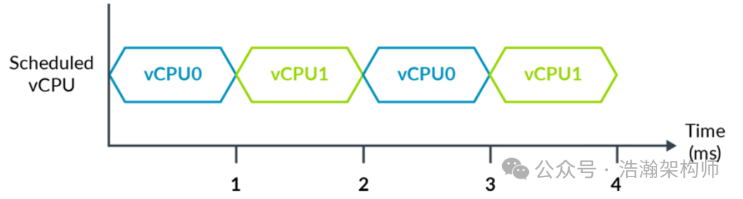
Figure 1-8 System with a Hypervisor that Hosts Two vCPUs
If the EL1 level does not intervene in the system time information, for example, if the software modules in the Kernel directly obtain time slice information from the CNTPCT_EL0 system register, then at the end of 4ms, both VM0 (vCPU0) and VM1 (vCPU1) believe they have run for 4ms. This is clearly inconsistent with the actual situation, as their actual execution time is 2ms each, and each VM has been stolen 2ms due to the Hypervisor’s scheduling. This situation is unacceptable for some EL1-level modules sensitive to running physical time slice information, such as the EL1 scheduling module, which allocates 4ms to each EL1-level process. After 4ms, the vCPU0 must perform an EL1-level process switch, but in reality, the process that has been switched out at the EL1 level has only executed for 2ms. This is still an ideal model; the actual situation will be even more complex because the physical CPU also needs to execute Hypervisor code and handle IRQs. Therefore, there needs to be a way to help EL1-level software modules obtain accurate running time. This problem is solved by the Generic Timer providing the CNTOFF register, as shown in Figure 1-9:
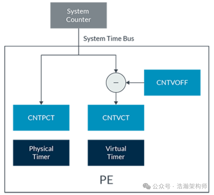
Figure 1-9 How the Virtual Counter is Generated
Let’s look at the description in the manual:
The virtual count allows a hypervisor to show virtual time to a Virtual Machine (VM). For example, a hypervisor could use the offset to hide the passage of time when the VM was not scheduled. This means that the virtual count can represent time experienced by the VM, rather than wall clock time.
Combining Figure 1-9, it is relatively easy to understand; the core point is that the Hypervisor maintains the count in CNTVOFF based on the actual execution situation of the vCPU. The software modules at the EL1 level read the time through CNTVCT, which actually reflects the real execution time of the vCPU, allowing various software modules within EL1 to make more objective decisions based on this time. Let’s look at the time after Hypervisor calibration, as shown in Figure 1-10:
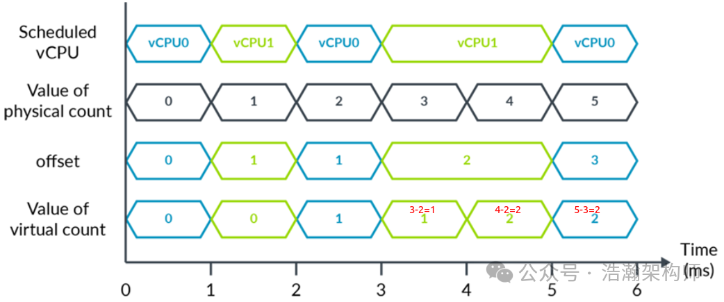
Figure 1-10 Example of Using a Virtual Timer
The above example is relatively easy to understand; we provide a simple explanation:
(1) From 3ms to 5ms, vCPU1 keeps executing, so the OFF value of vCPU1 remains at 2, as the CPU was scheduled to vCPU0 during the period from 2ms to 3ms.
(2) Based on (1), the Virtual timer count for vCPU1 at 4ms is 3-2=1, and at 5ms, it is 4-2=2.
(3) Similarly, the Virtual timer count for vCPU0 is also an algorithm; you can calculate it yourself.
Conclusion
In this article, we started by introducing the requirements of the time subsystem, clarifying the background of time subsystem virtualization. Based on the architecture of the single system time subsystem, we summarized the classic Generic Timer virtualization architecture in conjunction with mainstream time subsystem virtualization schemes. Finally, we introduced the significance of the Generic Timer working in a virtualization scenario with a specific usage example. Thus, our introduction to the ARM Generic Timer will temporarily conclude here. We will likely summarize a few articles on the Linux subsystem in the future, but please do not stop exploring; our articles are still relatively rough, and there are many details worth studying. For example, the Event Stream mentioned in previous articles, the unified Timer view of various nodes in concurrent scenarios, etc., are quite interesting. Please stay tuned, share, comment, and like. Thank you all.
Reference
[00]<80-Virt-ARCN-T-I0001_Timer.pdf>
[01]<80-Virt-ARCN-T-I0002_System-Timer-Virtualization.pdf>
[02]<learn_the_architecture_generic_timer_en.pdf>
[03]<80-LX-T-wx0001_从硬件到软件-Linux时间子系统全栈解析.pdf>
[04]<79-LX-LD-yk-Linux-Driver-Foundation.pdf>
[05]<79-LX-LK-LKD-ch-3rd.pdf>
[06]<79-LX-LD-s003-Linux设备驱动开发详解4_0内核-3rd.pdf>
[07]<80-LX-LK-cl0010_深入理解Linux时间子系统.pdf>
[08]<arm_cortex_a75_core_trm_100403_0301_01_en.pdf>
[09]<arm_cortex_a720_core_trm_102530_0001_04_en.pdf>
[10]<arm-dsu-120_trm_102547_0201_07_en.pdf>
[11]<DDI0500J_cortex_a53_trm.pdf>
[12]<SysReg_xml_A_profile-2024-03.pdf>
[13]<IHI0069H_gic_architecture_specification.pdf>
[14]<80-V-KVM-k0007_Linux虚拟化KVM-Qemu分析(七)_timer虚拟化解析.pdf>
[15]<80_NM495_1_F_MPSS_TIMER_SERVICES_DEBUG_GUIDE.pdf>
[16]<80-Virt-T-yx0001_Reducing-Timer-Overhead-in-Virtual-Machines.pdf>
[17]<80-Virt-T-yx0002_Heart_ticking_for_a_guest_running_on_FreeBSD_ARM_hypervisor.pdf>
[18]<80-Virt-T-yx0003_Understanding-KVM-and-Virtualization-on-ARM64.pdf>
[19]<80-Virt-T-yx0004_Generic-Interrupt-Controller-Version-3-Virtualization.pdf>
[20]<80-Virt-T-yx0005_Sorin-2009-Fault-Tolerant-Computer-Architecture.pdf>
[21]<80-82727-100_REV_AG_Software_Developer_Resources_For_SA83x7P.pdf>
[22]<DEN0057A_b_Paravirtualized_Time_for_Arm_based_Systems_v1_0.pdf>
Glossary
SoC – System on a Chip
DVFS – Dynamic Voltage Frequency Scaling
LDO – Low Dropout Regulator
OPP – Operating Performance Point
MLME – MAC sublayer management entity
PLME – PHY sublayer management entity
DSAP – Destination Service Access Point
SSAP – Source Service Access Point
vDSO – virtual dynamic shared object
NTP – Network Time Protocol
jiffies – a moment; an instant
SBSA – Server Base System Architecture
GIC – Generic Interrupt Controller
PPI – Private Peripheral Interrupt
WDT – watchdog timer
PLL – Phase-Locked Loop