While sitting on the high-speed train from Shanghai to Beijing, the long journey indeed makes one feel bored (I couldn’t get a direct train, so I had to go slowly, stopping at each station. It’s frustrating, even in the era of high-speed trains. It reminds me of the time I spent hours on a green train returning home during university breaks, haha). So, I felt a bit inspired to write and couldn’t help but sigh—spring has truly arrived! Why the quotes around ‘spring’? I believe everyone understands, haha. It’s nice; I can leisurely express my thoughts while traveling…
Actually, after spending so much time on ARM development, I’ve long wanted to share insights about the crucial issue of interrupt priority. Unfortunately, on one hand, explaining this issue thoroughly would require considerable effort, and on the other hand, my increasing busyness has made me lazier about writing, haha. So, taking advantage of the boredom on the train, I decided to roll up my sleeves and tackle this topic, as it’s a waste to let such important content gather dust in my mind, haha. Let’s get to the point; if I talk too much, it will be awkward when the train arrives, cough cough…
The need for interrupt priority configuration mainly arises when the system has multiple possible interrupt sources. To ensure reliable execution of code, we must consider two realistic issues. First, if two or more interrupts occur simultaneously, pending requests reach the CPU, and the CPU must decide which interrupt service routine to respond to first. The second issue arises when the CPU is currently responding to one interrupt service, and another interrupt request comes in—should it be allowed to interrupt the current service to respond to the new request? This is what we commonly refer to as the interrupt nesting issue. Don’t tell me you haven’t considered this (if that’s the case, I can only say that it’s irresponsible to handle microcontrollers this way, as it could introduce potential risk bugs into the project). If that’s the case, my writing would be in vain, haha. So, here’s the main topic: how do the currently popular ARM Cortex-M4 and M0+ cores address these two issues? Since these two cores have some differences in interrupt priority management (even though both use NVIC and SCB registers), I will discuss them separately. Additionally, since interrupt priority management is a kernel issue, you won’t find this information in the official manuals of major semiconductor manufacturers; we can only trace back to the ARM website for this information. I recommend that those interested download the M4 and M0+ core manuals from the ARM website and take a look; you might find unexpected insights, haha:
ARM Cortex-M0+ Interrupt Priority and Nesting
Both the M0+ and M4 cores manage interrupt priorities through the NVIC and SCB registers. Here, I assume everyone is aware that ARM interrupt sources are divided into core interrupts and IRQ interrupts (I’m afraid if I elaborate further, it will never end, haha). The management of IRQ interrupts is led by NVIC, while core interrupt management is led by SCB. Let’s first discuss the priority issue of IRQ interrupts (the enabling and disabling of interrupts is not within the scope of this article). Open the M0+ core manual and locate the NVIC_IPR register (Interrupt Priority Registers) as shown below:
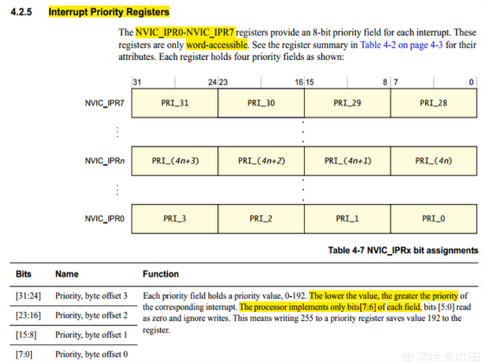
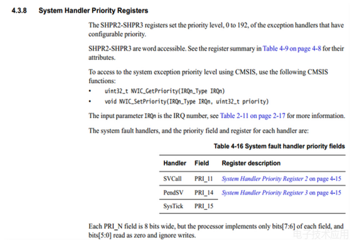
Note the highlighted sections; from these, we can abstract several core issues. First, there are a total of 8 NVICIPR registers, and each register manages 4 IRQ interrupts. A quick multiplication reveals why the M0+ supports a maximum of 32 IRQ interrupt sources. Adding 16 core interrupts gives a total of 48 interrupt sources. Thus, the M0+ is relatively straightforward to manage, but M4 will be more complicated, haha. The second issue is that lower configuration values in the priority register indicate higher corresponding interrupt priorities. The third issue is that only the highest two bits [7:6] of each PRIxx’s 8 bits are valid, meaning that the M0+ effectively has only four priority levels: 0, 1, 2, and 3, with 0 being the highest priority. The fourth issue, which I mention last because it is easily overlooked, is that these registers are word-accessible, meaning they can only be operated on by words. Do not use byte pointers to configure the priority of a single interrupt just to show off your programming skills. Regarding the nesting issue, it is relatively simple for the M0+: as long as the corresponding interrupt has a higher priority, it can preempt any lower-priority interrupt service. For core interrupts, their priorities are managed by the SCB module’s SCB_SHPR register, as shown in the figure below. In practice, we often use the system tick interrupt, and its priority configuration is the same as that of NVIC, so I won’t elaborate further. Additionally, I want to mention that if we do not configure priorities, the default behavior is that the lower the vector number of the interrupt source, the higher its priority. However, as I mentioned earlier, I strongly recommend configuring the priorities of each interrupt based on actual needs to avoid potential risks.
ARM Cortex-M4 Interrupt Priority and Nesting
I mentioned earlier that although the M4 instruction set is backward compatible with the M0+, there are differences in interrupt priority management. Due to the larger number of interrupt sources in the M4 (up to 256), its interrupt priority management is somewhat more complex. However, it is crucial to pay close attention, as we often use it, but I can assure you that not everyone’s usage is correct. Why? Let me break it down further (don’t worry, it’s not over yet, haha). Let’s look at the diagram below:
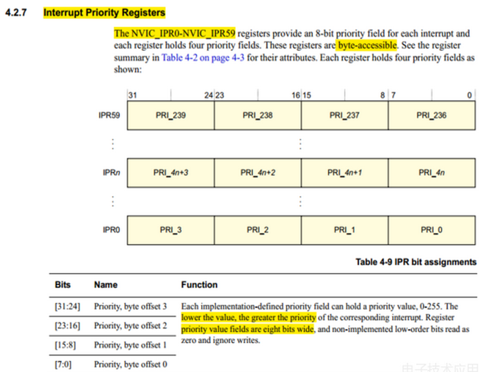
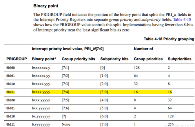
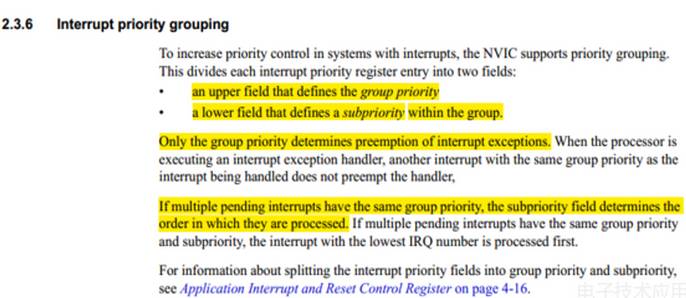
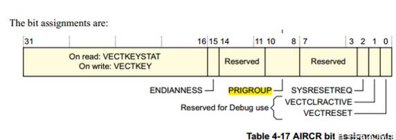
Continuing with the highlights from the previous diagram: first, the M4 supports up to 16 + 4 * 60 = 256 interrupt sources; second, these 60 registers can be operated on by bytes (we can show off our pointer skills here, haha); third, like the M0+, smaller values indicate higher priorities. Finally, the biggest difference is that each 8-bit data can define its interrupt priority. At this point, a question arises: does this mean that the M4 can have up to 256 priority levels? I can only say that everyone is overthinking it, haha. Let’s continue to look at the diagram; it can be seen that PRIGROUP defines how these 8-bit data are allocated between group priority and subpriority. As for what these two priorities mean, let’s refer to the second diagram and carefully understand it while I take a sip of water… Ok, back to it. From the following two diagrams, we can see that in the M4 core, interrupt priority management is divided into two parts: group priority and subpriority. Group priority manages preemption priority (whether it can nest), meaning that a high group priority interrupt (lower value) can preempt a low group priority interrupt (higher value). However, if the group priorities are the same, even if the subpriority of the new interrupt is higher than that of the currently executing interrupt, it cannot preempt it. Some of you might ask, what’s the use of subpriority? Haha, as shown in Diagram 2, when multiple interrupt requests occur simultaneously with the same group priority, the interrupt with the higher subpriority can execute first, while the lower subpriority must temporarily wait. Haha. The role of PRIGROUP is to configure how the NVIC’s 8-bit data field is allocated between preemption priority and subpriority. Generally, it’s best to allocate 4 bits to each, allowing up to 16 priority levels for each. Where does PRIGROUP come from? Haha, it is actually one of the three bits in the SCB_AIRCR register, as shown in Diagram 3.
Whew… Finally, I’ve managed to write out this issue. Now I can free up some space in my mind for other issues, haha. Additionally, while I wrote extensively about the theory, ARM has already provided these function APIs in the CMSIS library header files (core_cm4.h and core_cm0plus.h). The reason I went through the trouble of writing this out is that I believe in understanding both the ‘what’ and the ‘why’. However, in closing, I will provide two configurations for interrupt priority settings for M0+ and M4 for reference, and I won’t elaborate further; to be continued:
M0+
NVIC_SetPriority(PORTA_IRQn, 1);
NVIC_SetPriority(PORTB_IRQn, 2);
M4+
NVIC_SetPriorityGrouping(0x03);
NVIC_SetPriority(PORTA_IRQn, NVIC_EncodePriority(0x03,1, 2));
NVIC_SetPriority(PORTB_IRQn, NVIC_EncodePriority(0x03, 2, 2));