Weight is an important unit in life, and it is even more crucial in industry. How many kilograms of raw materials were added in the production process? How many kilograms of waste were generated, and so on… These data are essential elements supporting the smooth operation of the entire factory.
So how do we measure weight in industry? We need to use a load cell!
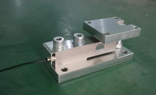
The principle of a load cell is to convert the gravitational force acting on the measured object into a measurable output signal in a certain proportion.
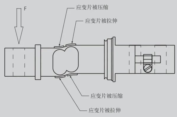
The measurement of Siemens load cells uses a strain gauge principle, where the strain gauge is fixed to an elastic body. The application of external force causes the elastic body to deform, and the strain gauge on the elastic body deforms accordingly.
Due to the change in the external shape of the strain gauge, its resistance value will also change accordingly. The strain gauges at the upper left and lower right corners are compressed, causing the resistance film to shorten and the resistance value to decrease. The strain gauges at the upper right and lower left corners are stretched, causing the resistance film to lengthen and the resistance value to increase.
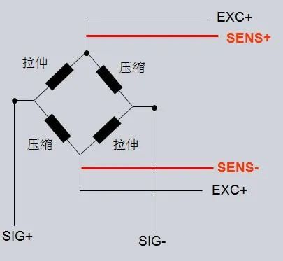
For each load cell, at least four strain gauges are connected together to form a Wheatstone bridge. When the sensor is subjected to force, the change in resistance of the strain gauges causes the bridge to become unbalanced. With the excitation voltage remaining constant, the magnitude of the output signal is proportional to the force applied to the sensor.
Load cells can generally be connected to PLCs or secondary displays for readings.
For four-wire sensors, there are only four cables shown in black in the diagram below, where EXC+ and EXC- are the excitation provided by the weighing module to the sensor, and SIG+ and SIG- are the output of the load cell; for six-wire sensors, there are two additional red wires, SENSE+ and SENSE-.What are their functions? These two wires are for compensation. When the distance between the sensor and the weighing module is relatively far, these two wires will provide compensation, making the measurement results more accurate.
In actual field use, due to complex working conditions, the distance between the load cell and the weighing module may be far. If the excitation voltage provided by the weighing module to the sensor is assumed to be 6V, then due to line loss, the excitation signal reaching the load cell is less than 6V. Under the same force conditions, the output signal of the sensor is proportional to the supply voltage, so the weighing module feeds back the actual supply voltage to the weighing module through a high-impedance loop, and the weighing module adjusts the output supply voltage using an internal comparator.
The weighing module can connect to both four-wire and six-wire sensors. If connecting to a four-wire sensor, it is necessary to short-circuit SENSE+ to EXC+ and SENSE- to EXC- at the junction box or weighing module side.
1. Use a load cell with a secondary display and PLC’s analog input. Why is a secondary display needed? Because the sensor generates a mv-level voltage signal due to the weight of the object, which the PLC cannot read directly, so a secondary display is needed for conversion. Speaking of conversion, everyone knows there will be some loss involved. This loss is not very large, but it can significantly impact precise measurements. I once worked on a device with a precision of 10g, and this loss had a substantial effect on the results. The advantage of this method is that it is inexpensive and does not require high demands on the PLC system, as 98% of PLCs on the market have analog input capabilities. However, the downside is that it cannot be applied in situations where high precision is required.
2. The most accurate method, which is also the most expensive, is to use a load cell with a PLC weighing module for measurement.

This method is the most accurate because the PLC connects to its own module without loss, and the reading speed is also very fast, applicable in various complex situations.
However, its disadvantage is that it places high demands on the PLC system. Firstly, the PLC needs to use a weighing module, and the prices of general weighing modules are relatively high. Additionally, a new weighing system needs to be calibrated before use. If the load cell is damaged and needs replacing, it also requires recalibration. The calibration of Siemens’ various series of weighing modules is not very simple and requires certain experience and skills, which we will explain later; thus, this technology is not suitable for beginners.
1. Care must be taken during installation to avoid damaging the sensor
The elastic body of the load cell is mainly made of alloy aluminum, so any vibration-induced impact or dropping can cause significant output data errors. For example, a sensor with a capacity of 10kg may be permanently damaged if accidentally subjected to a force of around 15kg. Therefore, when installing a load cell, it is essential to handle it with care.
2. Install according to its design requirements strictly
Depending on the equipment process, it may be installed horizontally or vertically, but the weighing part of the sensor must closely match the measured object, and the weighing part and the measured object must not contact other force points, or it will lead to inaccurate measurements.
3. Sometimes it is necessary to use three or even more load cells to measure the same object, and the contact surfaces of these sensors with the weighing device must be level; otherwise, uneven force will affect the measurement results. Although slight tilting of the level can be adjusted through resistors in the junction box, the adjustment capability is limited and not conducive to accurate weighing, so it is best to keep it level during installation.
1. Junction Box; When using multiple load cells, a junction box is a necessary tool that can unify multiple sets of weighing data, reducing the workload of the weighing module.
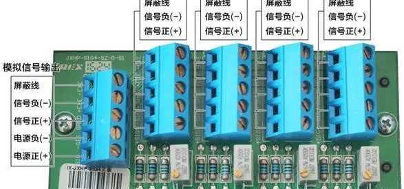
However, it is also prone to issues during use.
First, attention must be paid to dust-proofing, waterproofing, and anti-static measures, and secondly, during use, it is essential to understand the meaning of each terminal to avoid connecting the wrong wires.
2. Cable Connections and Shielding
The signals from the sensor are ultimately transmitted via cables, and for such high-precision signals, even a little interference can lead to data instability.
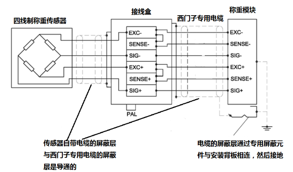
Therefore, connections must be carried out strictly as shown in the diagram above.
3. Programming Precautions: Can filtering be used?
In actual industrial sites, there are many interferences, so many people are accustomed to using programming methods for filtering. Filtering can also be used for weighing, but it should be noted that filtering introduces signal lag. If it is merely for observation and measurement, there is no problem, but if calculations or control based on measurement results are involved, it will lead to inaccuracies in weighing results, which everyone should be aware of.
(Source: Technical Training)
『This article is copyrighted by the original author. If there is any infringement, please contact for deletion.』
Editor: Shen Binfang
Reviewer: Hu Ying
Auditor: Li Guoqing