 Arduino Sensors: HS-S01A Infrared SensorArduino Sensors: HS-S02P Infrared Sensor (Obstacle Avoidance)Arduino Sensors: HS-S03P Ultraviolet SensorArduino Sensors: HS-S05P Sound SensorArduino Sensors: HS-F07P Active BuzzerArduino Sensors: HS-S08P Flame SensorArduino Sensors: HS-S09LB Raindrop SensorArduino Sensors: HS-S09PC Soil Moisture Sensor
Arduino Sensors: HS-S10P Fog Sensor
Arduino Sensors: HS-S11-L Gas Sensor
Arduino Sensors: HS-S20P Ambient Light Sensor
Arduino Sensors: HS-S21P Tilt SensorArduino Sensors: HS-S22P Grayscale SensorArduino Sensors: HS-S24P Digital Temperature SensorArduino Sensors: HS-S26A Temperature and Humidity SensorArduino Sensors: HS-S28P Rotary Potentiometer
Arduino Sensors: HS-S31P Touch Sensor
Arduino Sensors: HS-S37PS Water Level Sensor
Arduino Sensors: HS-S38P Human Body Sensor
Arduino Sensors: HS-S40P Hall Magnetic Sensor
Arduino Sensors: HS-S45P Barometric Pressure Sensor
Arduino Sensors: HS-S46P Weighing Sensor
Arduino Sensors: HS-S59P Slot Type Photoelectric Sensor
Arduino Sensors: HS-S70P Heart Rate and Blood Oxygen Sensor
Arduino Sensors: Infrared Receiver Module
Arduino Sensors: Infrared Transmitter Module
Arduino Sensors: Clock Module
Arduino Sensors: Rotary Encoder Module
Arduino Sensors: Dual-axis Joystick Module
Arduino Sensors: Gyroscope Module
Arduino Sensors: Voice Broadcast Module
Arduino Sensors: Voice Recognition Control Module
Arduino Communication Module: Bluetooth Module
Arduino Power Module: Motor Driver Module
Arduino Control Module: Self-locking Button ModuleArduino Storage Module: SD Card Module
Arduino Control Module: Conductive Switch Module
Arduino Execution Module: Electromagnet Module
Arduino Detection Module: Ultrasonic ModuleArduino Interaction Module: Button Switch Module
01Basic Knowledge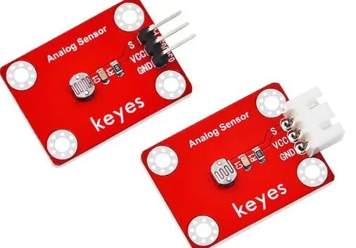 Model:NoneName:Photoresistor SensorSeries:Optical Detection SensorDescription:This is a light intensity detection module based on a photoresistor (LDR), which can convert ambient light intensity into an analog voltage signal. The stronger the light, the lower the output voltage; the weaker the light, the higher the output voltage. It features a simple structure, sensitive response, and low cost, making it a core component for automatic dimming, light control switches, and ambient light monitoring.Usage Scenarios:Smart home automatic lighting (e.g., automatically turning on lights at dusk and off at dawn); agricultural greenhouse supplementary light control (turning on supplementary lights when light is insufficient); interactive toy devices (switching between day/night modes based on ambient light); industrial equipment light control protection (automatically reducing screen brightness in bright environments); primary and secondary school science experiments (exploring the relationship between light intensity and resistance), in line with the practical requirements of the “Guidelines for Artificial Intelligence General Education in Primary and Secondary Schools (2025 Edition)”; environmental light indication devices designed for visually impaired individuals (issuing warning sounds in bright light).Interdisciplinary Integration:Physics, MathematicsMaterials ScienceInformation TechnologyEthical Education:Light data (e.g., indoor light changes) may indirectly reflect user activity patterns, requiring privacy protection; sensor detection accuracy is affected by the environment (e.g., window obstructions), necessitating the design of fault tolerance mechanisms; the recycling and disposal of photoresistors in electronic waste must consider material environmental protection; the differing light needs of various populations (e.g., suitable brightness for children and the elderly) reflect inclusive design; over-reliance on automatic light control may reduce energy-saving awareness, requiring a balance between technological convenience and proactive savings.Note: Images are sourced from the internet, and products are based on actual purchases.
02Technical Parameters
Working Principle:
The core of the module is a photoresistor (LDR), whose resistance value changes significantly with light intensity: in a dark environment, the resistance can reach several megaohms; in bright light, the resistance can drop to several thousand ohms. The module forms a voltage divider circuit with a fixed resistor in series, converting the resistance change of the photoresistor into a voltage change (the stronger the light, the smaller the voltage drop across the photoresistor, resulting in a lower output voltage). The microcontroller reads the output voltage through AD conversion and converts it into light intensity (usually expressed as a relative value or in lux).
Parameter Analysis:
G(GND): Power input negative/cathodeV(VCC): Power input positive/anode levelS(Signal):Signal output interface
Photoresistor Model: GL5516 (commonly used model)
Light Detection Range: 10-10000 lux
Resistance Change Range: Dark resistance ≥ 1MΩ (0 lux), Bright resistance ≤ 5kΩ (10000 lux)
Response Time: ≤ 10ms (time for light change to stabilize signal)
03Code Example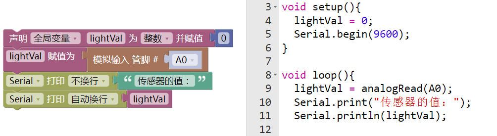
The link pin is A0.
04Safety Measures
1. Power off before wiring, confirm the positive and negative terminals of VCC and GND; reverse connection may damage the voltage divider circuit;
2. Do not scratch the surface of the photoresistor with sharp objects, as it will damage the photosensitive layer and affect detection accuracy;
3. Avoid prolonged exposure to strong light (e.g., direct sunlight), as it may accelerate component aging;
4. In humid environments, the module must be sealed; moisture can cause oxidation of the resistance pins and poor contact;
5. When soldering, keep the soldering iron temperature ≤ 300℃, and soldering time ≤ 3 seconds to prevent high temperatures from damaging the photosensitive layer;
6. If the signal drifts during debugging, check for obstructions blocking the sensor (e.g., wires, fingers);
7. When storing for a long time, wrap with opaque materials to prevent aging of the photoresistor during storage.
05Extensions
Students can try the following methods:
1. Create a “smart desk lamp”: link with the HS-F17P relay module to automatically turn on the light when the light is below 30% and turn it off when above 70%;2. Build a “light-controlled curtain”: combine with the HS-F04P motor driver module to close the curtain for shading in strong light and open it for lighting in weak light;3. Design a “sunlight recorder”: in conjunction with the HS-S30P clock module, record light changes at different times of the day, storing data in the HS-S64-L SD card module;4. Develop an “interactive light and shadow device”: in conjunction with the HS-F01P RGB LED module, the stronger the light, the dimmer the LED, and the weaker the light, the brighter the LED, achieving a dynamic balance effect.

— Previous Recommendations —