Prerequisite: A few days ago, a colleague asked me about Camera issues, specifically how to test Camera signals. Since we communicated over the phone, I thought that simply discussing D-PHY wouldn’t be very effective, as D-PHY is just a physical layer specification. The signal transmission of the Camera is based on the CSI-2 protocol layer; understanding the protocol layer in conjunction with the measured waveforms is essential to know what kind of signals are correct. Today, I am writing an article to look at D-PHY Camera in conjunction with CSI-2. I hope that by the end of this article, you will understand how CSI transmits Camera data. For those who are not familiar with D-PHY, you can refer to my previous articles.Interpreting the MIPI DPHY ProtocolHand-tearing MIPI DPHY Parameter Testing – 1Hand-tearing MIPI DPHY Parameter Testing – 2Hand-tearing MIPI DPHY Parameter Testing – 3Camera CSI-2 Basics: To start from the basics, the first thing you need to clarify is that the Camera data of resolution (m*n) is transmitted frame by frame, where a frame of data consists of n lines (line), and each line consists of m pixels. The Camera transmits data from left to right and from top to bottom.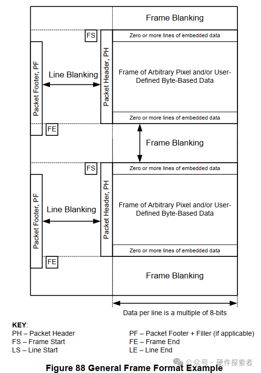 Figure 2-1, Frame Transmission Example I will explain using a top-down approach. If a Burst diagram can help understand 50% of the D-PHY physical layer content, I feel that if you grasp this Figure 2-1 in CSI-2, you will have understood 50% of the CSI protocol content. Some students may not understand how to read such diagrams, so let me explain: you should look from top to bottom and from left to right. As mentioned earlier, the Camera image is transmitted in units of frames. The FS in this diagram is the frame header, followed by a group of embedded data (optional), then the data for line 1, followed by the data for line 2… and finally the last line of data, followed by another group of embedded data (optional), and then the frame tail FE. What does Frame Blanking mean? It is the time interval between one frame and the next; data transmission occurs in high-speed mode, and there will be a period of LP mode time between different frames. Frame blanking refers to this LP mode time. What does Packet Blanking mean? It is the time interval between one packet and the next; data transmission occurs in high-speed mode, FS&FE are short packets, and line data is long packets. The transmission of packets is hung on the D-PHY Burst, as shown in Figure 2-2 (understand this diagram carefully; I have added notes), different packets use different Bursts, and the LP mode time between two packets (two Bursts) is Packet Blanking.
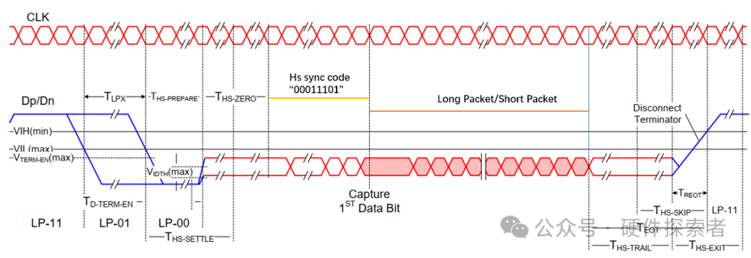 Figure 2-2, Long Packet/Short Packet Format Previously, I mentioned long and short packets, which may not be understood. Below, I will introduce short packets. As shown in Figure 2-3, a common short packet is FS (Frame Start) and FE (Frame End); a short packet is a 32-bit data packet, which roughly consists of data type, virtual channel, checksum, etc.
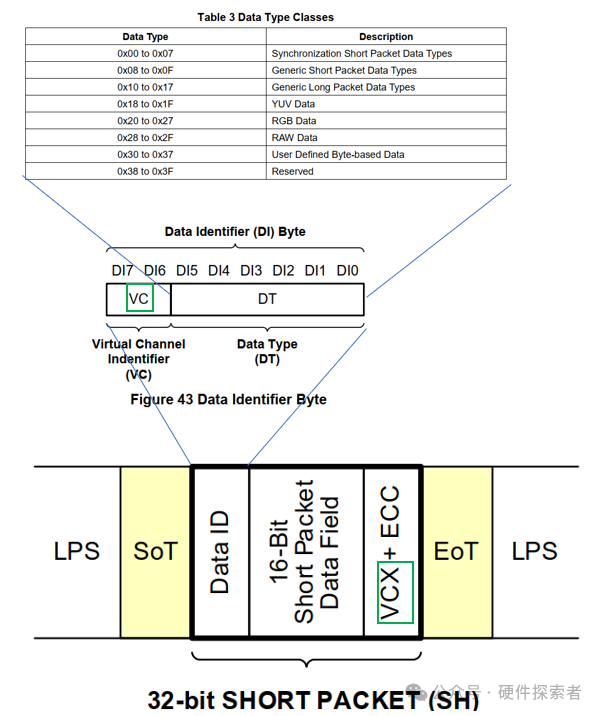 Figure 2-3, Short Packet Definition Next, I will introduce long packets, as shown in Figure 2-4. Long packets consist of 3 parts: 32bit-PH, DATA, 16bit-PF.
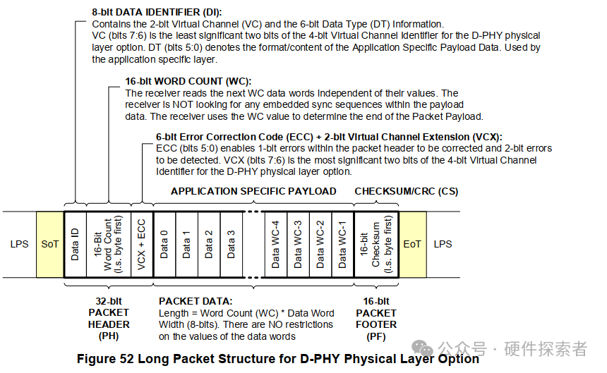 Figure 2-4, Long Packet DefinitionWaveform Analysis: Analyzing the waveform collected from a 640*480, 1-lane, 60FPS, Raw10, 800M BR camera using an oscilloscope, we use the waveform to understand the protocol and the protocol to read the waveform. Yellow is CLK+, green is CLK-, blue is D0+, and red is D0-. From Figure 3-1, we can see that this Camera transmits at a speed of 60FPS/16.7ms. The transmission of pixel data occurs in HS mode, and we can see that during the time of one frame, there is not always high-speed signal transmission; there is a period of high level time, which is the Frame Blanking mentioned above. Enlarging the image gives us Figure 3-2, which shows that the current Camera only used 10.9ms for data transmission. Remember these two times; we will perform calculations later.
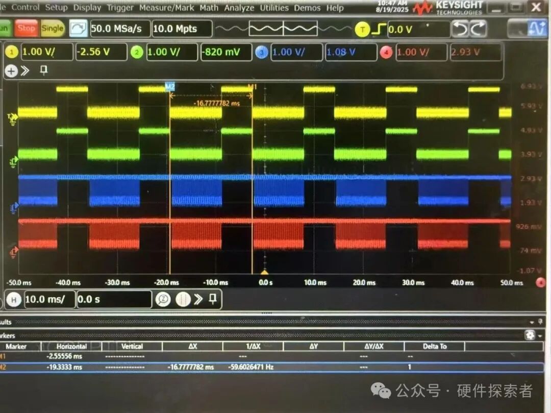 Figure 3-1, Frame Transmission – 1
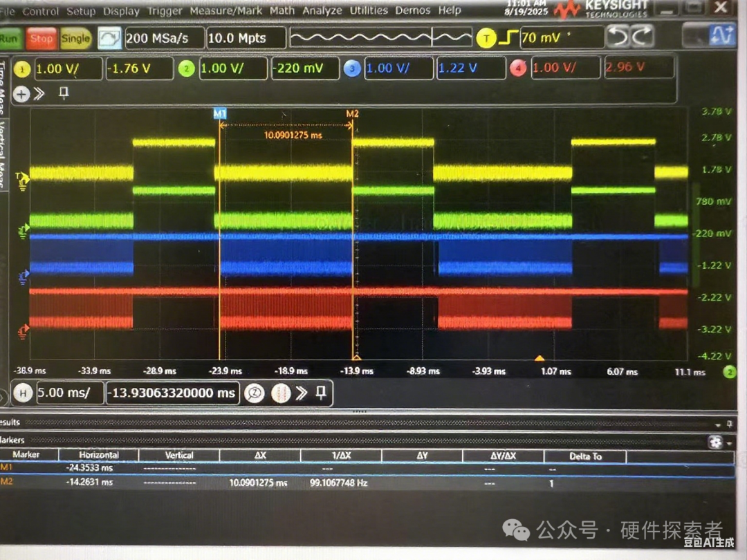 Figure 3-2, Frame Transmission – 2 We expand the high-speed part of the frame transmission, which contains one Burst long packet, as shown in Figure 3-3. The time for one Burst long packet is 20.98us, and each Burst packet transmits one line of data. We expand it as shown in Figure 3-4, measuring the time for high-speed data transmission as 8.13us. Not every Burst long packet is a high-speed transmission part; the high level part is the Packet Blanking mentioned above.
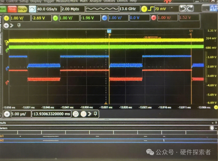 Figure 3-3, Line Transmission – 1
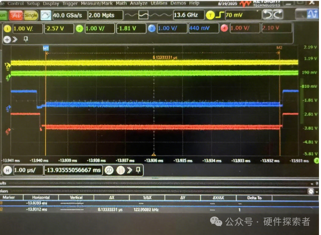 Figure 3-4, Line Transmission – 2Calculation: The measured time for transmitting line pixel data is 8.13us, and our BitRate is 800M. So how many bits were transmitted in 8.13us? 8.13us/(1/800M)=6500. As mentioned earlier, the data transmission format is RAW10, meaning 1 pixel is represented by 10 bits, so 6500/10=650 pixels. Careful students may ask how this is larger than 640? 1) I included the time for PH and PF, 2) the error in timing. Now, you understand that one Burst (excluding FS, FE, Embedded data) is one line of data, right? Next, we calculate; from Figure 3-2, the frame internal data transmission time is measured to be 10.1ms, and from Figure 3-4, the time for one Burst is 20.98us. So how many lines were transmitted? 10.1ms/20.98us= 480. This matches our actual Camera parameters.Appendix:1) Frame Header Waveform Careful students may not have seen the FS information; I believe they cannot see it because the image is so small. Let me enlarge it for everyone. As shown in Figure 4-1, we see that after CLK enters high-speed mode, there are two Burst pulses, where the first is the 32-bit FS short packet, and the second pulse is the Embedded data (to briefly explain, the Embedded data is a long packet that transmits some auxiliary information), and after a slight delay, the first line, second line…. data begins to be transmitted. I won’t continue to elaborate for everyone; just a brief mention.
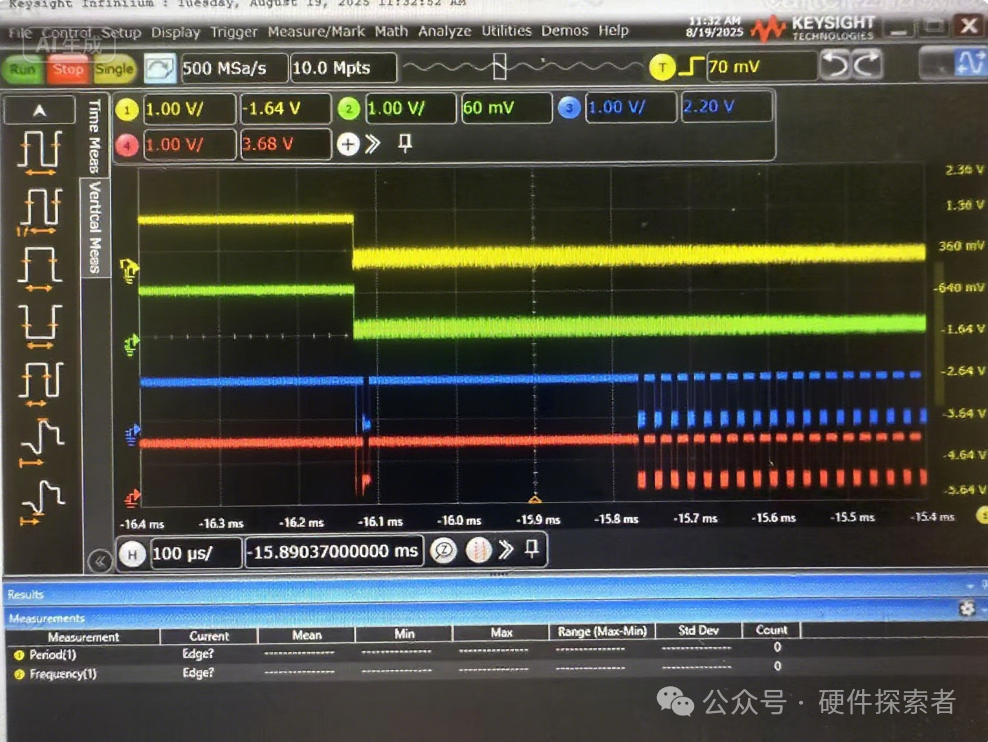 Figure 4-1, Frame Header Part2) Data Format Data transmission is in Raw10 format, meaning one pixel is represented by 10 bits. However, the CSI protocol stipulates that the transmission unit must be bytes of 8 bits. Let’s see how Raw10 is transmitted, as shown in Figure 4-2, and there are different image formats; refer to the definitions in the specification for more details.
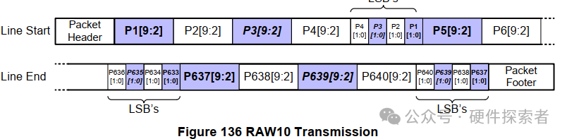 Figure 4-2, RAW10 Format3) Multi-lane Transmission How does a Camera transmit if it has multiple lanes? This diagram shows how the data is arranged, as shown in Figure 4-3.
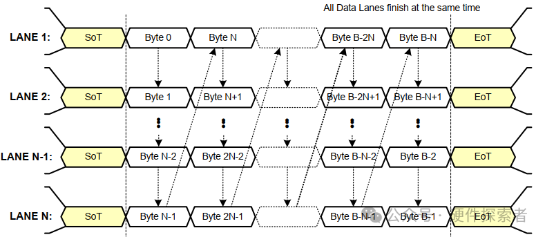 Figure 4-3, Multi-lane Transmission4) Virtual Channels Can one CSI only transmit the image of one Camera? The answer is no. For example, if there are 5 cameras, but the SOC only has one CSI, what should we do? Our solution is to aggregate the data from these cameras into one CSI using FPGA, utilizing different VCs for transmission. Those who have done USB communication should be familiar with this concept; the USB protocol also has this concept. The image of multi-virtual channel interleaved transmission is shown in Figure 4-4; pay attention to the details of this image; every letter and every color has its meaning, so understand it carefully.Figure 4-4, Virtual Channel Interleaved TransmissionConclusion: This article introduced the CSI protocol based on D-PHY; some details were not fully written. The key is that we learned how to read the protocol. Additionally, the CSI protocol also has a C-PHY version, which differs slightly from D-PHY. If you don’t understand, you can refer to my article on the application of MIPI C-PHY in XR to review the CSI protocol. If you want to learn more details about the CSI-2 protocol, follow the public account and reply “0004 download” to get it.