In the field of automation, there are devices that cannot be operated manually, such as high-pressure gates and corrosive liquid valves. Typically, we use computer software to control these devices through a combination of PC-based host software and a microcontroller.
Design a controller with four relays that can be controlled via software on a computer.
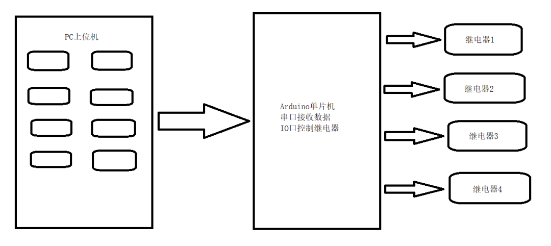
This requirement consists of two parts: a microcontroller and software on the computer. The computer has eight buttons to control the on and off states of the four relays.
The general framework is to establish communication control between the PC and MCU via serial port. When the MCU receives data from the PC, it will analyze the received content and process it accordingly.
Before starting the project, let’s define the communication parameters as follows:
|
|
9600 bps (Bits Per Second)
|
|
|
8 |
|
|
|
|
|
|
This defines the communication settings, which follow the common format of 9600, 8N1. The communication commands are defined as follows:
We specify that when the PC sends “1” to the MCU, Relay 1 turns on; when it sends “2”, Relay 1 turns off, and so on.
Next, we will explain the design from three aspects: the circuit, the microcontroller program, and the host program. We need to design the driving circuit for the microcontroller and the relay. You can choose to use an Arduino microcontroller with four LEDs to simulate the effect of relays.
A relay is an electronic control device that has a control system (input circuit) and a controlled system (output circuit), commonly used in automatic control circuits. It is an “automatic switch” that uses a small current to control a larger current.
Thus, it plays roles in automatic regulation, safety protection, and circuit conversion. The relay coil is represented by a rectangular box symbol in the circuit. If the relay has two coils, two parallel rectangles should be drawn. The relay’s symbol is marked with the letter “J” inside or next to the box. The relay contacts can be represented in two ways: one is to draw them directly on one side of the rectangle, which is more intuitive.
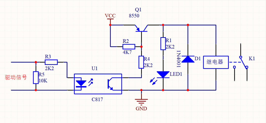
Here, I am using an optocoupler relay. A relay uses a low voltage, low current to control a high voltage, high current component. To avoid high voltage breakdown of the MCU, I used an optocoupler IC_C817. This IC consists of a light-emitting diode and a photodiode. When our driving signal lights up the LED, the photodiode detects the light source and conducts. Resistor R3 is a current-limiting resistor to protect the IO port and GND; resistor R5 is a pull-down resistor to ensure the IO defaults to a low level.
In the driving circuit on the right, we use an S8550 transistor as a driver. When the photodiode of the C817 conducts, the current from VCC can pass through transistor Q1 to close the relay. Resistor R2 is a pull-up resistor to ensure Q1 is in a cutoff state by default, and resistor R4 is a current-limiting resistor to protect the optocoupler. Resistor R1 and LED1 serve as a status indicator, with R1 being the current-limiting resistor for LED1 to protect it. When the relay closes, current passes through the coil, which we need to treat as an inductor. When the relay releases, it generates a reverse current that could potentially damage the entire circuit; diode D1 serves to protect against this.
Now let’s talk about Arduino. Arduino is a convenient, flexible, and easy-to-use open-source electronic prototyping platform that includes hardware (various models of Arduino boards) and software (Arduino IDE).
It is built on an open-source simple I/O interface and has a development environment similar to Java and C language (Processing/Wiring). It consists of two parts: the hardware part connects the circuit using an Arduino board; the other part is the Arduino IDE, the programming environment on your computer. You simply write the program code in the IDE, upload it to the Arduino board, and the program tells the Arduino board what to do.
Arduino can sense the environment through various sensors and control lights, motors, and other devices to feedback and influence the environment. The microcontroller on the board can be programmed using the Arduino programming language, compiled into a binary file, and burned into the microcontroller. Programming for Arduino is done using the Arduino programming language (based on Wiring) and the Arduino development environment (based on Processing). Projects based on Arduino can include only Arduino or a combination of Arduino and other software running on a PC, communicating with each other (e.g., Flash, Processing, MaxMSP).
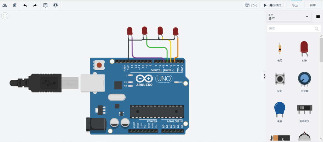
You can use any version of Arduino; here I am using Arduino UNO. I am using LEDs to simulate the relay effect.
This is a simulation website https://www.tinkercad.com/, feel free to explore.
Lower Computer Driver Code
We have defined the communication frequency and format; now we need to write the MCU code. Our lower computer uses Arduino UNO, and its programming syntax and download method are straightforward. We need to implement a serial reading function to print the current data from the serial port to the screen.
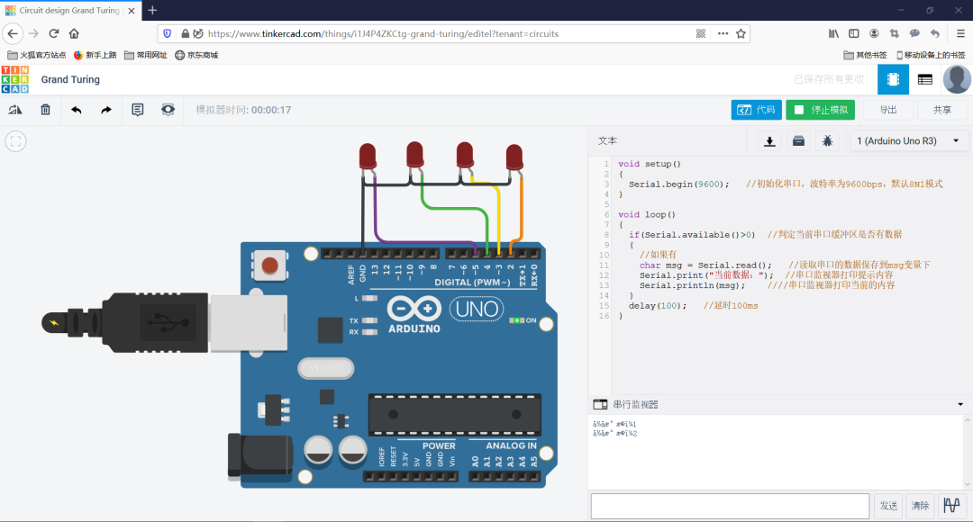
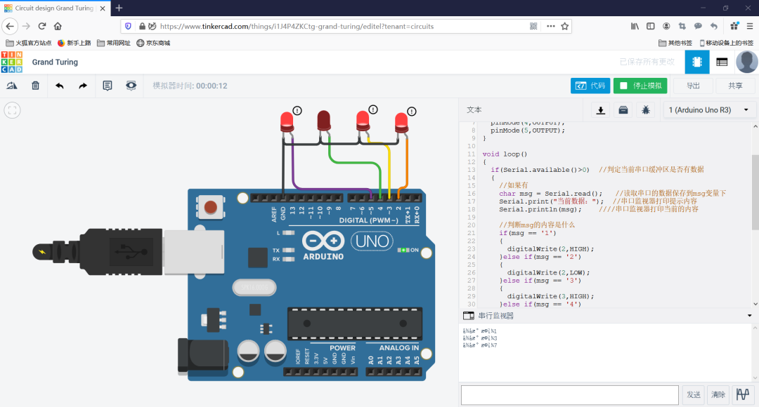
void setup(){ Serial.begin(9600); // Initialize serial port, baud rate 9600 bps, default 8N1 mode}void loop(){ if(Serial.available() > 0) // Check if there is data in the serial buffer { // If yes char msg = Serial.read(); // Read data from the serial port and save it to msg variable Serial.print("Current data:"); // Print prompt message to serial monitor Serial.println(msg); // Print current content to serial monitor } delay(100); // Delay 100 ms}
This is the Arduino serial reception program, which will display the content read from the serial port with a prompt in the serial monitor.
This is the content I tested in simulation, and it works fine. The garbled text is due to the current browser not supporting the Unicode encoding format for Chinese characters. Now let’s modify the code to add input content judgment based on the existing code. As follows:
void setup(){ Serial.begin(9600); pinMode(2,OUTPUT); pinMode(3,OUTPUT); pinMode(4,OUTPUT); pinMode(5,OUTPUT);}void loop(){ if(Serial.available() > 0) // Check if there is data in the serial buffer { // If yes char msg = Serial.read(); // Read data from the serial port and save it to msg variable Serial.print("Current data:"); // Print prompt message to serial monitor Serial.println(msg); // Print current content to serial monitor // Check the content of msg if(msg == '1') { digitalWrite(2,HIGH); }else if(msg == '2') { digitalWrite(2,LOW); }else if(msg == '3') { digitalWrite(3,HIGH); }else if(msg == '4') { digitalWrite(3,LOW); }else if(msg == '5') { digitalWrite(4,HIGH); }else if(msg == '6') { digitalWrite(4,LOW); }else if(msg == '7') { digitalWrite(5,HIGH); }else if(msg == '8') { digitalWrite(5,LOW); } } delay(100); // Delay 100 ms}
I now input 1, 3, and 7 into the serial port and press Enter; the corresponding LEDs light up. Here, if we replace the LEDs with relays, we can achieve industrial control. We have tested this in simulation successfully, and now we can purchase materials for physical testing. The list is as follows:
|
Arduino Development Board
|
|
|
|
|
|
|
|
Host Computer Development
C# is an object-oriented programming language developed by Microsoft, derived from C and C++, running on the .NET Framework and .NET Core (completely open-source and cross-platform). It was introduced at the Microsoft Professional Developers Conference (PDC).
C# is the latest achievement of Microsoft researcher Anders Hejlsberg. C# looks remarkably similar to Java; it includes features such as single inheritance, interfaces, and a syntax almost identical to Java, compiling to intermediate code for execution. However, C# differs significantly from Java; it incorporates a feature from Delphi and is directly integrated with COM (Component Object Model), making it the main character of Microsoft’s .NET Windows network framework.
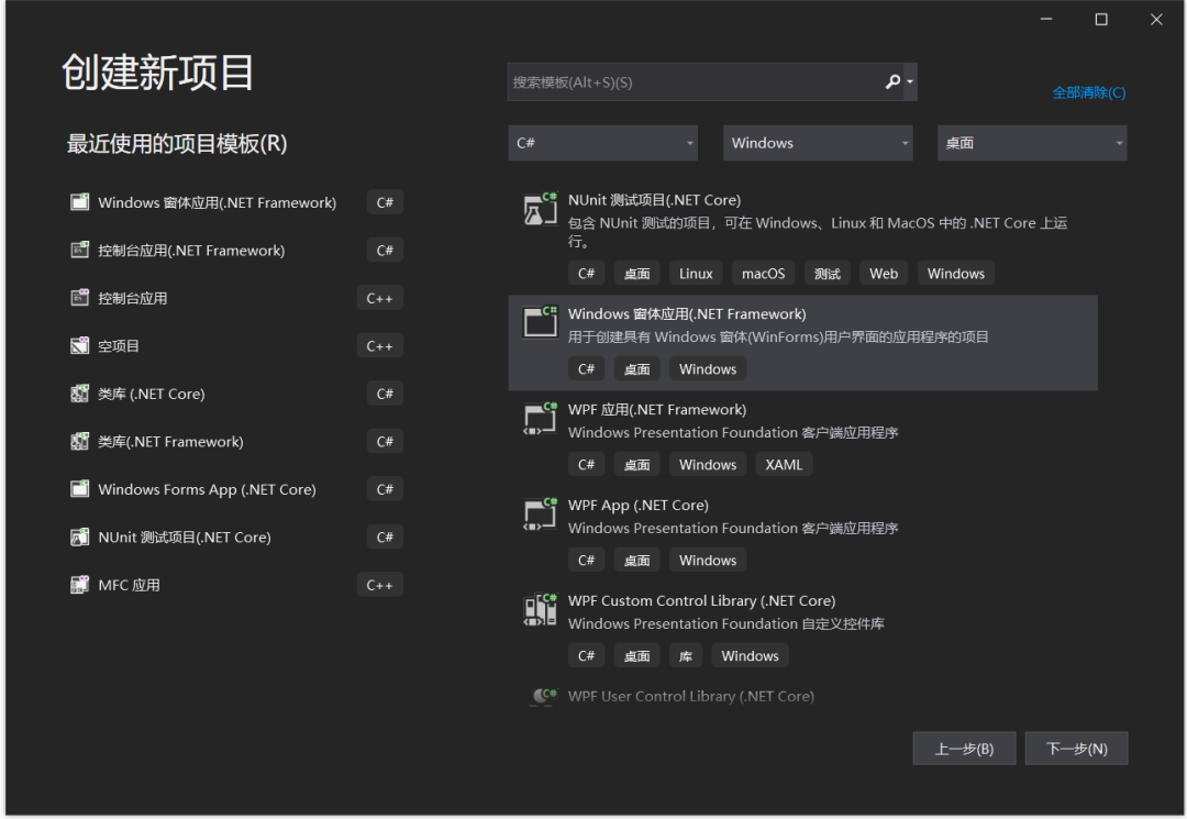
We will create a Windows Forms application in Visual Studio as follows:
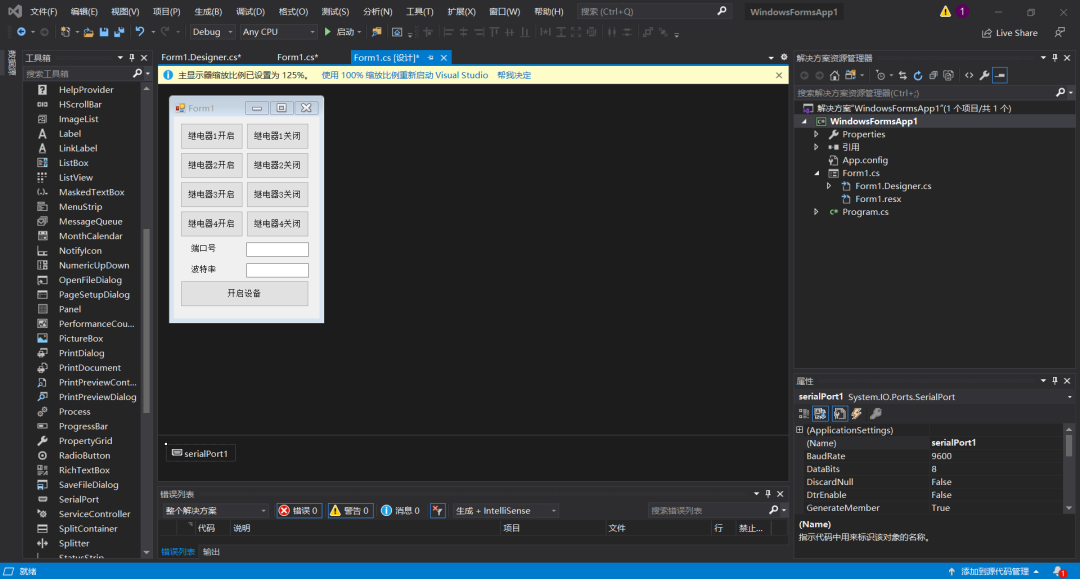
We will layout the UI interface as shown below.
Here, I will introduce the signal and slot mechanism again. In our host computer, pressing different buttons will send out different commands. When a button is pressed, a signal is generated, and there will be a part of the program specifically designed to handle this signal and execute the corresponding action. Therefore, this part can also be called the signal triggering and slot execution mechanism.
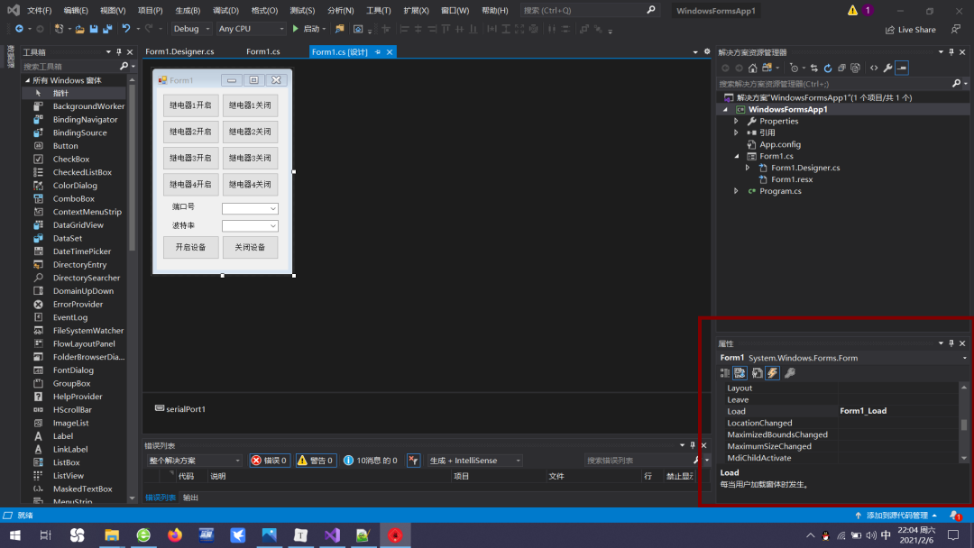
private void Form1_Load(object sender, EventArgs e){ for (int i = 1; i < 20; i++) { comboBox1.Items.Add("COM" + i.ToString()); // Loop to add content to comboBox1 } comboBox1.Text = "COM1"; // Change comboBox1 content to COM1 comboBox2.Text = "9600"; // Change comboBox2 content to 9600}
Here, we define a function called Form1_Load, which initializes the page when we start. We add some port configuration information to the corresponding option boxes. This part of the code is placed in the load event of the Form1 control.
Next, we have eight buttons to control the relays. When a button is pressed, we need to send the corresponding data through code as follows:
// When button 1 is pressedprivate void button1_Click(object sender, EventArgs e){ serialPort1.Write("1"); // Send data 1, control Relay 1 to turn on}// When button 2 is pressedprivate void button2_Click(object sender, EventArgs e){ serialPort1.Write("2"); // Send data 2, control Relay 1 to turn off}// When button 3 is pressedprivate void button3_Click(object sender, EventArgs e){ serialPort1.Write("3"); // Send data 3, control Relay 2 to turn on}// When button 4 is pressedprivate void button4_Click(object sender, EventArgs e){ serialPort1.Write("4"); // Send data 4, control Relay 2 to turn off}// When button 5 is pressedprivate void button5_Click(object sender, EventArgs e){ serialPort1.Write("5"); // Send data 5, control Relay 3 to turn on}// When button 6 is pressedprivate void button6_Click(object sender, EventArgs e){ serialPort1.Write("6"); // Send data 6, control Relay 3 to turn off}// When button 7 is pressedprivate void button7_Click(object sender, EventArgs e){ serialPort1.Write("7"); // Send data 7, control Relay 4 to turn on}// When button 8 is pressedprivate void button8_Click(object sender, EventArgs e){ serialPort1.Write("8"); // Send data 8, control Relay 4 to turn off}
This part is the content for executing the eight button slots, sending the corresponding content via the serial port. Finally, regarding the operations to open and close the port, buttons 9 and 10 are responsible for this. The content is as follows:
// When button 9 is pressedprivate void button9_Click(object sender, EventArgs e){ try { serialPort1.PortName = comboBox1.Text; // Serial port name is the content of option box 1 serialPort1.BaudRate = Convert.ToInt32(comboBox2.Text); // Communication frequency is the content of option box 2 serialPort1.Open(); // Open the serial port button3.Enabled = false; // Disable button 3, the button for opening communication button4.Enabled = true; // Enable button 4, the button for closing communication } catch { MessageBox.Show("Port error, please check the port.", "Error"); // If any statement in try fails, execute this }}// When button 10 is pressedprivate void button10_Click(object sender, EventArgs e){ try { serialPort1.Close(); // Close the serial port button3.Enabled = true; // Enable button 3 button4.Enabled = false; // Disable button 4 } catch { MessageBox.Show("Close failed.", "Error"); // If any statement in try fails, execute this }}
This is the slot execution code for opening and closing the serial port in C#. We assign the contents of the two combo boxes to the serial port number and baud rate, and then use the open() and close() functions to open and close the serial port. Since this part of the code is not safe, errors during execution could lead to a crash, so I used try…catch… statements for handling. If opening or closing fails, it will terminate the current execution and pop up a prompt box for a warning.
During the opening and closing of the port, the “Open” button and “Close” button are also controlled through their Enable properties. At this point, our host computer design is complete. We will insert the Arduino we previously made into the computer, run the software we wrote, select the corresponding port number and baud rate, and we can control the four relays with the host software. Students who need the complete project code can message the GuYueJu WeChat public account for it~
This tutorial explains how to achieve hardware and software integration for industrial control based on Arduino and C#. This tutorial is just an introductory guide to collaborative development of hardware and software. There is still much to cover regarding C# host computer development, and we will gradually update content on this in the future~
“mbot Robot – Lichuang EDA Design Driver Board” From scratch PCB design teaching, quickly get started with circuit board design, starting from schematic drawing, guiding you through PCB wiring, and finally teaching you to get a free PCB!