Abstract
Based on the openness and ease of use of the Arduino controller of the open source control platform, an experimental teaching module with the Arduino microcontroller as the core has been added to the original electronic technology comprehensive experiment. Using the pulse width modulation technology (referred to as PWM technology) in the Arduino microcontroller, the microcontroller adjusts the input voltage of the two DC motors according to the received infrared signal, thereby controlling its speed ratio, and then controlling the motion trajectory of the dot laser reflected by the two eccentric mirrors on the motor, forming a pattern by using the visual residual effect, and verifying the correctness of the laser pattern through simulation experiments designed by MATLAB. The new teaching module expands the content of welding control circuits in the traditional experimental teaching of comprehensive electronic technology design, enriches the experimental teaching content, strengthens the cultivation of students’ programming ability and electronic technology comprehensive design ability, and stimulates students’ interest in learning.
Keywords: Arduino; Teaching Reform; Pulse Width Modulation Technology (PWM Technology); Computer Programming
The comprehensive electronic technology design experiment is an important comprehensive course for the Optoelectronic Information and Physics majors. After undergraduate students learn the theoretical knowledge of electronic technology, they can exercise their experimental skills through hardware design, communication control, and software programming, thereby enhancing their comprehensive electronic technology design ability. In the electronic technology comprehensive design experiment course offered by the School of Physics at Sun Yat-sen University, students are required to solder and install control circuits to control the input voltage of two DC motors, which reflect the laser through two different speed eccentric rotating mirrors to form specific laser patterns. By changing the voltage ratio of the two DC motors, different laser patterns can be obtained[1]. Through soldering control circuits, students can achieve several specific voltage ratio output circuits, and by using a sound acquisition module, they can switch between several different voltage ratios. However, the above method leads to a single output pattern form, and due to a single faulty electronic component in the soldered circuit, troubleshooting experimental issues becomes difficult, bringing some inconvenience to experimental teaching. Arduino, as a convenient, sensitive, and easy-to-use open-source electronic development platform, has been widely used in the development of various circuit systems[2-4]. By introducing the Arduino microcontroller into the electronic technology comprehensive design experiment course, it not only expands the development design methods of control circuits but also allows students to program independently based on C language by introducing other sensor modules, enriching the experimental teaching content. By introducing the Arduino microcontroller control mode, the traditional soldering electronic circuit content is expanded into a coherent mode of “principle design circuit connection software programming”, enhancing students’ initiative and interest in learning, reducing the failure rate caused by improper circuit soldering in electronic technology experiments, and promoting the improvement of teaching quality.
1 Experimental Principles
This paper takes the Arduino microcontroller as the core component of the control circuit, combined with the L293D chip, infrared signal receiving module, laser, DC motor, eccentric rotating mirror, and other hardware, to achieve infrared signal communication and PWM signal output control of the DC motor speed, thereby changing the shape of the laser pattern.
1.1 Introduction to Arduino
Arduino is an open-source electronic technology creative platform developed by teachers at the Interaction Design Institute in Milan, Italy in 2005. Arduino includes hardware (various types of Arduino development boards) and software (integrated development environment for code compilation, Arduino IDE, and graphical programming environments provided by third parties such as Mind+, Scratch3.0, etc.). Due to Arduino’s programming having similarities with commonly used programming languages such as Java and C++, the Processing/Wiring development environment[4] is easy to get started with, versatile, and inexpensive, making it widely used in electronic technology design and interactive product development, and it is favored by many electronic technology developers.
The Arduino UNO development board is currently the most commonly used Arduino development board, with the ATmega328 MCU microcontroller at its core, generally having the following structure:
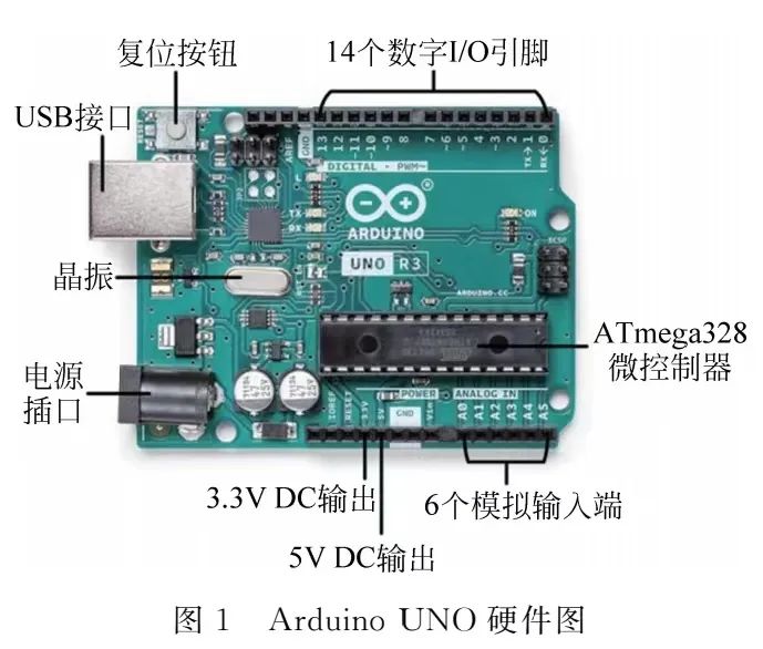
(1) 1 USB interface, which can communicate with a computer via a USB data cable to upload Arduino IDE programs to the development board, and can also supply power to the development board with a voltage of 5V;
(2) 1 power socket, which can use a DC power supply to power the development board with a voltage of 9V, enabling the development board to drive larger power external devices;
(3) 14 digital I/O pins for digital signal input and output, of which 6 pins support PWM mode output;
(4) 6 analog input terminals for analog signal input;
(5) A 16MHz crystal oscillator, used to generate the clock frequency required by the microcontroller;
(6) 1 reset button, 1 5V DC output, and 1 3.3V DC output, and other interfaces[2].
Arduino IDE is a program compiler dedicated to Arduino, which is the integrated development environment of Arduino. It encapsulates the microcontroller’s registers in the core library and is a secondary encapsulation of the microcontroller program code GCCAVR. Developers only need to understand the function of each port on the Arduino development board, write program code, and upload it to the Arduino development board without needing to understand the internal register settings of the development board, reducing the difficulty of using the Arduino development board. At the same time, Arduino is also compatible with GCCAVR, allowing developers to program registers directly for projects with high real-time requirements[3].
Because of the secondary encapsulation of the microcontroller program code by Arduino IDE, users do not need to understand the internal hardware structure and register settings of the microcontroller; they only need to understand the function of each port to use basic C language knowledge to write program code and enable Arduino to achieve the desired function.
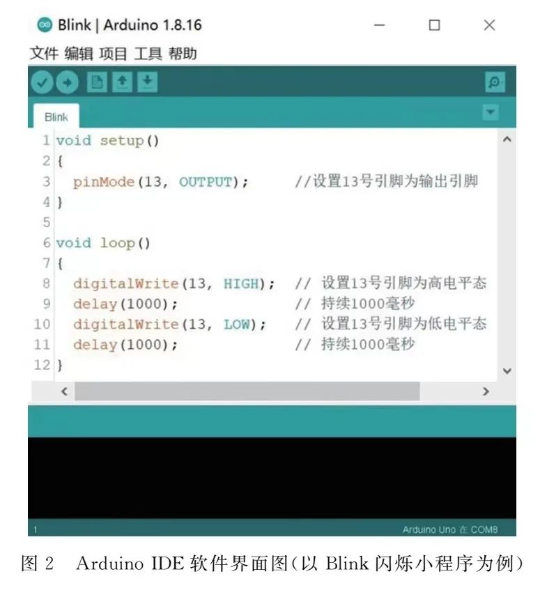
For example, using the built-in blinking program in Arduino, upload the code shown in Figure 2 to the Arduino UNO board, and connect the positive electrode of the LED to pin 13, and the negative electrode to the GND pin, you can see the bulb blinking alternately. Through this simple program, the purpose of controlling electronic components using the Arduino board can be achieved.
In addition, Arduino development boards can connect to other input and output modules to achieve more functional designs. Developers write programs in Arduino IDE and upload them to the Arduino development board. By connecting sound sensors, infrared receiving modules, ultrasonic receiving modules, and other input components to digital input interfaces or analog input terminals, signal reception, and action collection can be performed, and by connecting DC motors, buzzers, displays, and other output components to digital output interfaces or PWM output terminals, signal transmission and action output can be performed, achieving the goal of perceiving and influencing the external environment[4,5].
1.2 PWM Modulation Technology
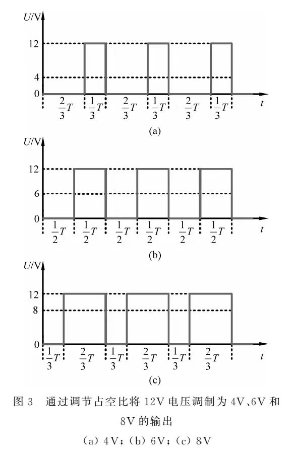
PWM (Pulse Width Modulation) is a pulse width modulation technology that modulates the output time of digital levels to change the pulse width, thereby obtaining the desired stable DC voltage output[6]. For a pulse signal with a period of T and an amplitude of Vpp, adjusting its high-level output time to th,  is called the duty cycle, and the equivalent obtained analog voltage value is
  . As shown in Figure 3, adjusting the duty cycle of a DC voltage signal with an amplitude of 12V to
  ,
,  and
and  , the obtained analog voltage values are 4V, 6V, and 8V of the PWM DC voltage signal.
Arduino achieves PWM output through counters and registers. The counter counts repeatedly between the minimum and maximum values according to certain rules. When the value of the counter matches the value set in the comparison register, the logic level of the digital output is switched, achieving modulation of the high-level output time[7].
The digital I/O pins 3, 5, 6, 9, 10, and 11 of the Arduino UNO development board support PWM output, with the PWM signal frequency output from pins 3, 9, 10, and 11 being approximately 490Hz, and approximately 980Hz from pins 5 and 6. The function analogWrite(pin,value) is a dedicated function in Arduino IDE for controlling PWM output, where pin is the number of the PWM output pin, and value is the duty cycle of the output pulse signal, with a range of 0~255, corresponding to the output analog voltage value of  .
.
2 Experimental Introduction
2.1 Traditional Circuit Soldering Experiment
The traditional experimental process uses clock timing triggers or sound control triggers, where students solder control circuit boards to achieve timed or sound-controlled changes in laser patterns. Figure 4 is a schematic diagram of the control circuit process.
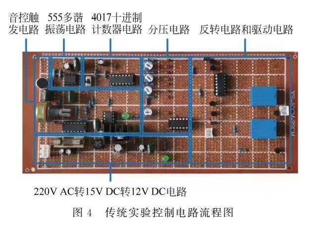
The timing trigger mode uses a 555 multivibrator circuit to output adjustable pulse signals; the sound control trigger mode uses amplification circuits and shaping circuits to stabilize sound signals into pulse signals. Under the rising edge of the square wave pulse signal, the decimal counter 4017 cyclically outputs Q0、Q1、Q2、Q3 four high-level outputs, which are then divided through a voltage divider circuit to obtain four different working voltages, thus controlling the direction and different speed ratios of the two DC motors through the inversion circuit and driving circuit. The laser reflects continuously through the eccentric mirrors on the two motors to form different laser patterns on a white screen[1,8].
The experiment requires students to solder complex control circuit boards, which can only achieve several specific voltage ratio output circuits, and the circuit is difficult to adopt other signal triggering modes. Due to the difficulty in troubleshooting experimental issues caused by a single faulty electronic component, the experiment is time-consuming, the output pattern form is single, and issues such as cold solder joints during the experiment lead to low extensibility of the experiment.
2.2 Improved Experiment Based on Arduino
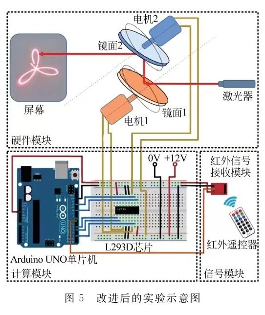
This paper introduces Arduino to expand the experimental approach, making the experiment more innovative. Figure 5 is a schematic diagram of the improved experiment. The control process is as follows: 1) Signal Module: Pressing the infrared remote control sends an infrared signal, which is received and read by the Arduino through the infrared signal receiving module; different keys correspond to different electrical signals in Arduino; 2) Computing Module: The Arduino calculates and controls the corresponding voltage ratio PWM analog voltage signal based on the received infrared signal, which is then amplified and drives the two DC motors through the L293D chip; 3) Hardware Module: The laser reflects continuously through the eccentric rotating mirrors of two different speeds, forming specific laser patterns on the screen. By changing the speed ratio of the two motors, different shapes of laser patterns can be obtained.
2.2.1 Infrared Signal Input
The Arduino microcontroller can connect with various input modules such as clock sensors, sound sensors, and light-sensitive resistors to achieve multiple signal input paths. This paper uses infrared signal input to control the experimental device.
The lower right part of Figure 5 shows the infrared signal receiving module and remote control. Connect the output interface of the infrared signal receiving module (i.e., the OUT pin on the module) to pin 7 of the Arduino UNO for signal transmission, and provide the module with working voltage through the 5V output port of the Arduino UNO. When the infrared signal emitted by the remote control is received, the built-in program of the receiving module demodulates and encodes the infrared signal, outputting a six-digit hexadecimal code.
In the Arduino IDE library manager, install the IRremote library file, and by calling the enableIRIn() function, the module can be triggered to receive infrared signals. The decode() function can be called to demodulate and encode the infrared signal into the corresponding six-digit hexadecimal code[9].
2.2.2 L293D Chip
Since the maximum output voltage of the Arduino microcontroller is 5V, which is insufficient to drive a 12V DC motor, this paper combines the L293D chip to implement the DC motor driving circuit. Figure 6 is the schematic diagram of the L293D chip. Pin 16 connects to a 5V power supply to provide working voltage for the chip’s control circuit; pin 8 connects to a 12V power supply to provide working voltage for the chip’s driving circuit. Pins 2, 7, 10, and 15 are control signal input pins; pins 3, 6, 11, and 14 are driving signal output pins used to output signals to drive the motor. Pins 1 and 9 are enable pins; when the enable pin is set to a high level, the corresponding input and output pins are activated, outputting a driving voltage that is in phase with the control signal[10].
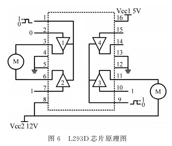
Connect one end of motor 1 to output pins 3 and 6 of the L293D chip. Set one of the input pins 2 or 7 to a high level and the other to a low level, forming a potential difference at the output pins to drive the motor to rotate. When different pins are set to high levels, the polarity of the potential difference changes, altering the motor’s direction.
One end of motor 2 connects to output pin 11 of the L293D chip, and the other end connects to ground. When input pin 10 is set to a high level, output pin 14 outputs a high voltage, forming a potential difference to drive the motor to rotate.
Input the PWM analog signal into the enable pins 1 and 9, and the corresponding output pins will output the same duty cycle PWM analog signal, achieving changes in the voltage across the motor terminals.
2.2.3 Program Design
Write the program on Arduino IDE to control the output of the PWM analog signal based on the input infrared signal. The program design is shown in Figure 7.
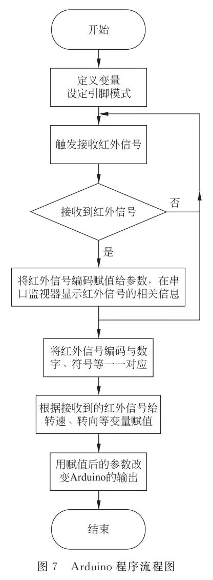
At the beginning of the program, define variables for pins, speed, direction, etc., and set the mode of the pins. Use the enableIRIn() function to trigger the infrared signal receiving module to receive signals, and use the decode() function to determine whether the infrared signal has been successfully received. If the infrared signal is received, the signal will be demodulated and encoded into a six-digit hexadecimal code and assigned to the variable results, which will be displayed in the serial monitor of the Arduino IDE; if no signal is received, the variables remain unchanged, and the Arduino output signal remains unchanged.
After receiving the infrared signal, use an if-else statement to map the infrared signal codes to the numbers 0~9 and symbols +, – and assign them to the variable Input. Based on the value of variable Input, the speed variable speed and direction variable Direction are changed.
To achieve separate control of the speeds of the two motors, define a variable channel. When the button “CH+” is pressed, channel=1, controlling motor 1; when the button “CH-” is pressed, channel=2, controlling motor 2.
To achieve multiple different voltage ratio outputs, define the speed variable to control the motor speed, assigning values to the speed variable corresponding to the numeric keys 0~9 at equal intervals from 0~255;
Since the laser patterns formed when motor 1 rotates forward and motor 2 rotates backward are the same as those formed when motor 1 rotates backward and motor 2 rotates forward, only the direction variable Direction is defined in the program to control the direction of motor 1 while keeping the direction of motor 2 unchanged.
Pass the above variables as function parameters and call the digitalWrite() and analogWrite(pin,value) functions to change the level state of the corresponding output pins and the duty cycle of the PWM signal, controlling the speed and direction of each motor.
3 Results Analysis
Upload the program to the Arduino, use the remote control buttons “CH+” and “CH-” to select the motor to control, and then set the output pin’s analog voltage value using the numeric keys 0~9, obtaining different output voltages, driving the motors with different speeds or directions through the L293D chip. The laser, carried by the eccentric mirrors of two DC motors with specific speed ratios, reflects continuously to form specific laser patterns on a white screen. By changing the different speed ratios of the two DC motors, different shapes of laser patterns can be obtained.
By distinguishing the motor’s direction change based on the positive and negative voltage ratios, the voltage ratios of the two DC motors are set to -9∶5, -3∶2, and 3∶2, obtaining the corresponding laser patterns on the white screen, as shown on the left side of Figure 11.
To verify the accuracy of the experimental design, theoretical calculations were also performed, and MATLAB software was used to simulate the formation process of the laser patterns. The theoretical analysis process is as follows:
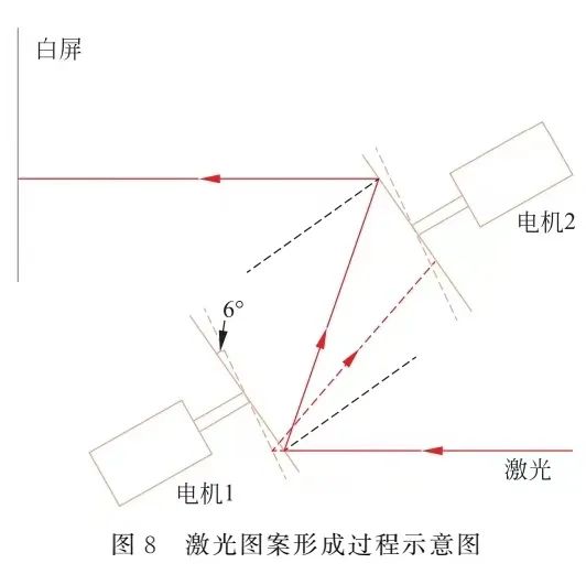
In the experimental device, the normal direction of the plane where the eccentric mirror on the motor is located is not parallel to the motor axis but exists at an angle of 3°. The positions of the two reflective surfaces of the mirrors on the motor under rotation are the two extreme positions, forming a 6° angle. The dot laser directly illuminates the eccentric mirror on the DC motor. Because the normal direction of the plane where the mirror is located is at an angle to the motor axis direction, when the motor rotates, the reflected dot laser does not point in a fixed direction but forms a conical surface, appearing as a circle or ellipse on the white screen. The laser reflected from the first mirror illuminates the second mirror, resulting in a second reflection, and the image displayed on the white screen is the superposition of two circular trajectories moving[11].
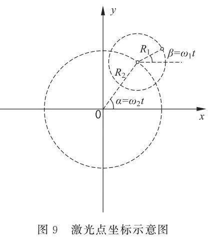
Establish a rectangular coordinate system on the white screen, as shown in Figure 9. Taking the horizontal direction as the x-axis and the vertical direction as the y-axis, let the x-coordinate of the laser point displayed on the white screen after two reflections be x, and the y-coordinate be y, then
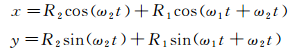
Where the radius of the circular trajectory formed by the first reflection is R1, the angular velocity is ω1, and the radius of the circular trajectory formed by the second reflection is R2, with the angular velocity ω2.
Using MATLAB software to conduct a simulation experiment on the formation process of the laser patterns, the code program is as follows.
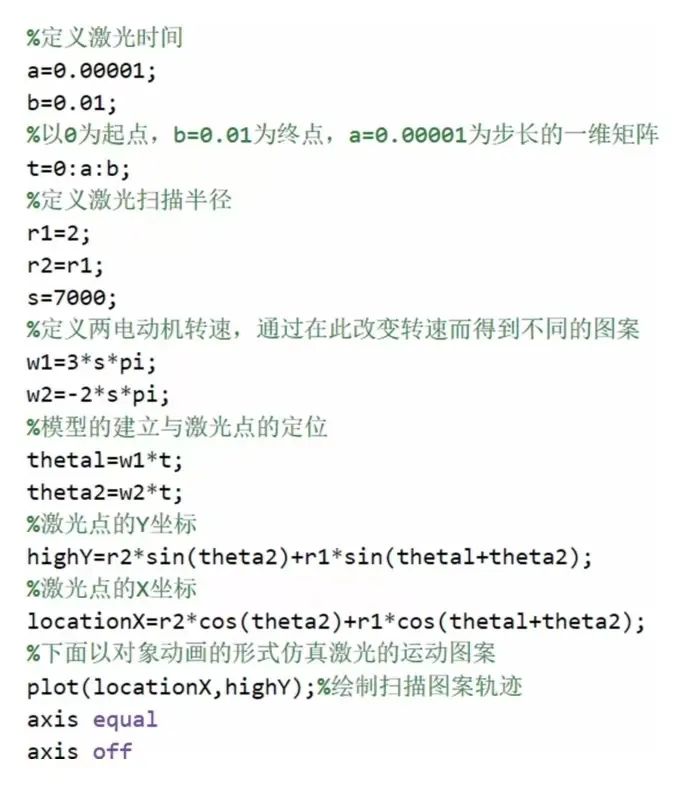
Modify the ratio of the two speed variables in the MATLAB code to -9∶5, -3∶2, and 3∶2, and adjust the laser timing appropriately. Run the program to obtain the corresponding simulated laser patterns, as shown on the right side of Figure 10.
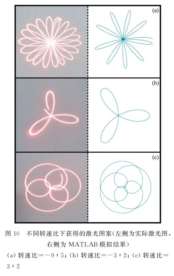
From the experimental results and simulation results, it can be seen that when the two motors rotate in opposite directions with speed ratios of 9∶5 and 3∶2, the laser pattern presents a petal shape. As the voltage ratio increases, the “petals” become narrower and more numerous; when the two motors rotate in the same direction with a speed ratio of 3∶2, the laser pattern forms a heart shape rotating around a point.
It should be noted that during the experiment, due to the initial phase difference in rotation of the two motors, the laser pattern slowly rotates around the center. Therefore, during the experiment, the actual laser pattern is captured by a smartphone camera, using an extended shutter time to achieve this; the simulated laser pattern obtained through MATLAB is realized by simultaneously plotting the trajectory equations of the laser points on a canvas. Because the smartphone’s shutter time is longer, and the simulated experiment plots the motion trajectory of the laser points within one cycle, when the speed ratio of the two DC motors is 9∶5 and the rotation directions are opposite, the number of “petals” observed in the experiment is significantly more than that in the MATLAB simulation results. However, the actual observed laser patterns are consistent with the simulation results, as the patterns rotate around the center. In the other two speed ratios, the actual laser patterns also rotate around the center (this is evident from the fact that the actual observed laser patterns do not form closed curves).
The actual experimental results are consistent with the simulation experimental results. Thus, we have achieved infrared remote control of the shape of the laser patterns using PWM modulation technology in Arduino.
4 Conclusion
By taking the Arduino microcontroller as the core and implementing the PWM modulation method to control the laser pattern in the electronic technology comprehensive design experiment, the traditional electronic experimental teaching has been enriched. By adjusting the duty cycle, controlling the output voltage, and generating various PWM signals, various laser patterns can be produced. This experimental design scheme utilizes the pulse modulation technology in the Arduino microcontroller, allowing students to design hardware connections, circuit designs, and software programming hands-on. After fully learning the basics of electronic technology, they can independently design a laser pattern system based on PWM modulation control, which can comprehensively cultivate students’ electronic technology comprehensive design and application abilities. The Arduino microcontroller experiment based on an open-source system is very suitable for undergraduates, combining physical measurements and optoelectronic technology to carry out various practical applications.
References
[1] Hong Lan, Cai Xiufen, Chen Min. Exploration and practice in self-designing electronic experiment teaching[J]. Laboratory Science, 2013, 16(3): 78-81.
[2] Cai Ruiyan. Principle and application of Arduino[J]. Electronic Design Engineering, 2012, 20(16): 155-7.
[3] Wu Hanqing. Play with Arduino electronic production[M]. Beijing: Mechanical Industry Press, 2016.
[4] Chen Lvzhu. Basic Arduino programming[M]. Beijing: Beihang University Press, 2014.
[5] Wang Xuqing. Research on the maker education model oriented to STEM education[J]. China Educational Technology, 2015, (8): 36-41.
[6] Wang Zhao’an, Liu Jinjun. Power electronics technology[M]. 5th ed. Beijing: Mechanical Industry Press, 2011.
[7] Shi Yishan, Cui Yansong. Principle exploration and practice of PWM based on Arduino[J]. 2019.
[8] Lin Yuanfang, Huang Yuanqing. A laser projector which obtains a composite pattern by reversibly adjusting the speed of a motor[J]. Application of Electronic Technique, 1999(10): 34-36.
[9] Liu Jingming. The design of an intelligent manipulator based on Arduino infrared control[J]. Technology Wind, 2019(12): 7-8.
[10] Cao Qingsong, Cheng Junliang. Design of wireless spherical mobile robot control system[J]. Machine Tool & Hydraulics, 2016, 44(17): 12-15.
[11] Liang Zhong, Yin Aihan. Analysis of the pattern of the automatic instrument of lasers romantic pattern[J]. Jiangxi Science, 1997(1): 1-6.
Funding Project: National College Student Innovation and Entrepreneurship Training Program Project (202210357); Sun Yat-sen University Undergraduate Teaching Quality Engineering Project (Sun Yat-sen University Academic Affairs [2022] No. 20, 74130-12220011).
Corresponding Author: Liang Feixiang, Male, Sun Yat-sen University Experimental Teacher, Research direction: Condensed matter physics, unconventional superconductivity, electronic technology experimental teaching, [email protected].
Citation format: Lin Bingquan, Shi Haoyu, Che Yu, et al. Application research of PWM modulation in Arduino in electronic technology experiments[J]. Physics and Engineering, 2023, 33(3): 80-87.
Cite this article: LIN B Q, SHI H Y, CHE Y, et al. Application research of PWM modulation in Arduino in electronic technology experiments[J]. Physics and Engineering, 2023, 33(3): 80-87. (in Chinese)