Analysis of NXP-MicroPython Demonstration Car Model
Introduction:
Hello to all car enthusiasts participating in the 19th Intelligent Vehicle Competition. As you may know, this year’s camera group is divided into three tracks, one of which is the NXP-MicroPython track, introducing a new programming language direction with Python as the main development language for the first time.
The use of Python as the development language in this track allows participants to avoid the troubles of IDEs (such as MDK, IAR, and ADS with Chinese paths, project settings, and debugger compatibility), and there’s no need to become familiar with additional tools (only a MicroPython development board and a Type-C data cable are needed to start development), thus shortening the time spent getting accustomed to the environment and IDEs, allowing participants to invest valuable time in application design and planning.
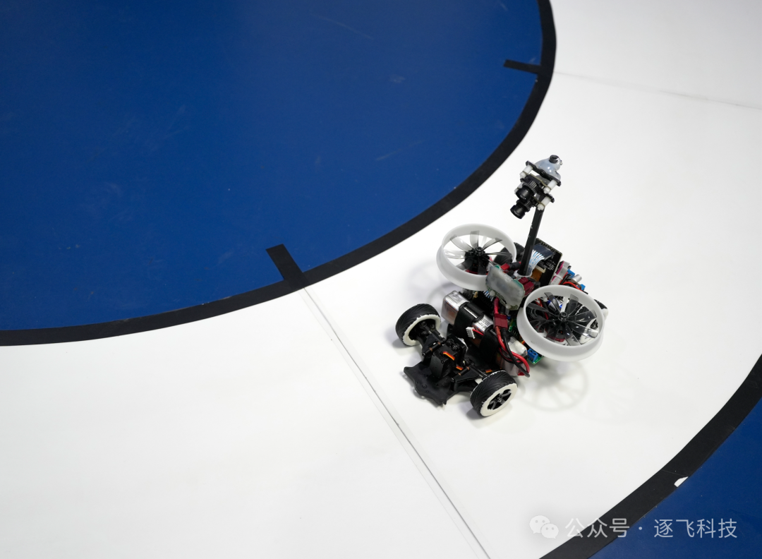
The competition tasks for the camera group are universal across the three tracks, but each MCU platform is restricted to its designated MCU. The MCU for the NXP-MicroPython track is limited to development boards based on NXP processors with MicroPython. According to the MicroPython track instructions, the specified RT1021 core board must be used. For specifics, please refer to the instructions:
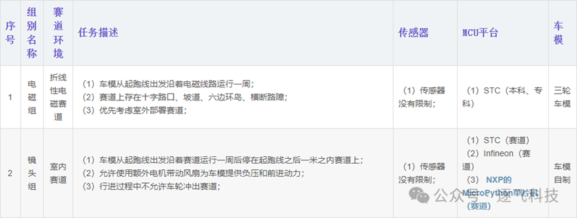
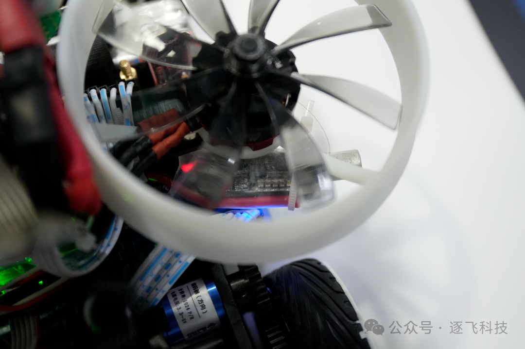
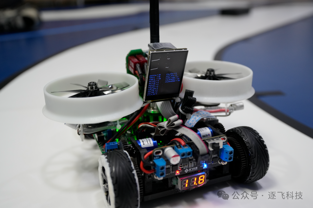
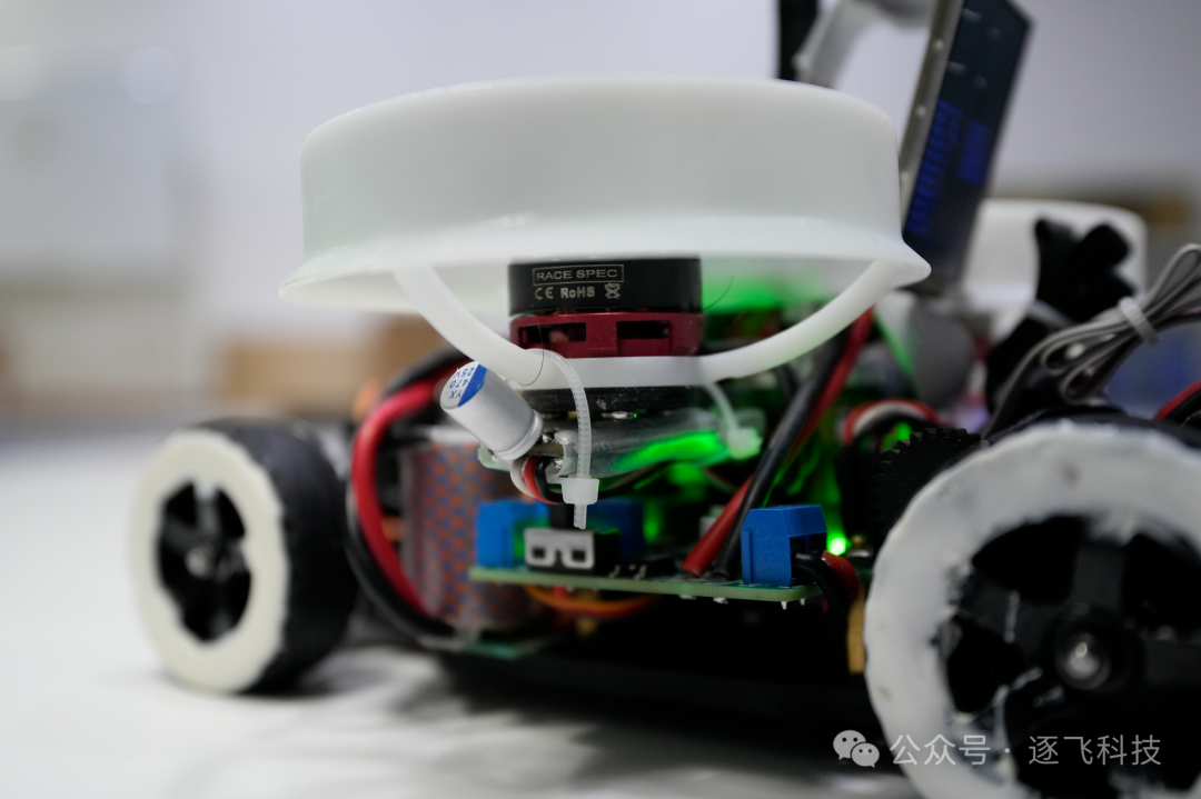
Unlike previous years where specific car models were designated, this year allows for custom car models and the addition of negative pressure fans, which is like adding wings to a tiger. I believe participants will truly feel the speed and passion. In this issue, we will use the demonstration car model as a medium to share the general thoughts and considerations for this group, hoping to help everyone clarify their ideas and smoothly create their own car model works to achieve good results in the competition.
1. Competition Task Content
Since the camera group’s track tasks are universal, Zhuo Da has already published them on CSDN. Students who haven’t read them carefully can check the rules blog link:http://t.csdnimg.cn/Q7lCe
They can also refer to the previously published article: Preparation Process and Ideas for the 19th Camera Group – Zhu Fei
In that article, we have detailed the competition task content for this year’s camera group, providing interpretations of this year’s camera group competition tasks and the basic work that needs to be prepared (which can be referenced except for the hardware list concerning the MCU).
Details related to the MicroPython track can also be found in the supplementary instructions published by Teacher Zhuo: Related Instructions for the 19th National College Student Intelligent Vehicle Competition Camera Group NXP MicroPython Track

This notice also provides compilation environment and related learning materials, which have been uploaded to Baidu Cloud. The link is:https://pan.baidu.com/s/1l0fn_c0V8xbtoS6rHBpd2g
Extraction code: 33ei

2. Brief Overview of MicroPython Development
According to the provided compilation environment and related learning materials, the NXP-MicroPython track recommends using Thonny software for development and debugging, as it can operate the file system of the development board and perform file operations:
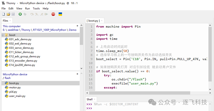
The total amount of code for the demonstration car model consists of only four files, with a total code length of no more than 800 lines, while traditional C language groups often involve multiple folders, dozens to hundreds of low-level files, and code lengths in the thousands.
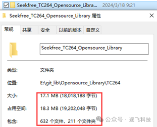
Using C language for development not only requires a good foundation in C but also familiarity with various peripherals’ drivers and resource allocation on the microcontroller, which takes considerable time to master at the low level.
In contrast, developing with Python simplifies this process. After a short period of reading the firmware manual and learning the interface usage through example programs, one can basically master all functionalities.
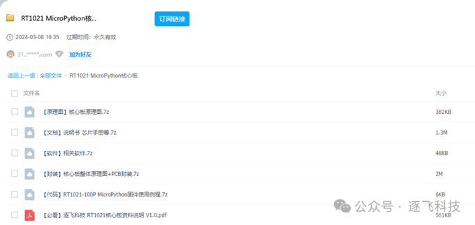
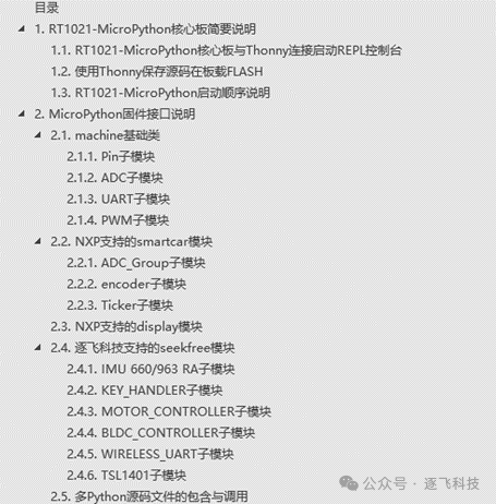
This is precisely what the introduction of Python in this track hopes to achieve: to dedicate more time to top-level application design. By reviewing the firmware manual, one can see that the usage methods for each module are quite simple and convenient:
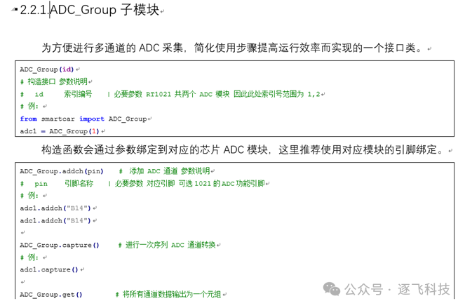
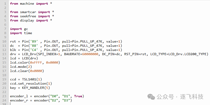
Only a basic understanding of Python is needed to develop, and multiple modules can be used directly with import:
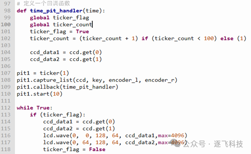
A comprehensive sensor library can automatically capture data that needs to be collected periodically:
Since the firmware manual in the materials has provided thorough usage guidance, there is no need to waste space describing it here. Everyone can refer to the firmware manual provided in the materials. Next, let’s move on to the related sharing of the demonstration car model.
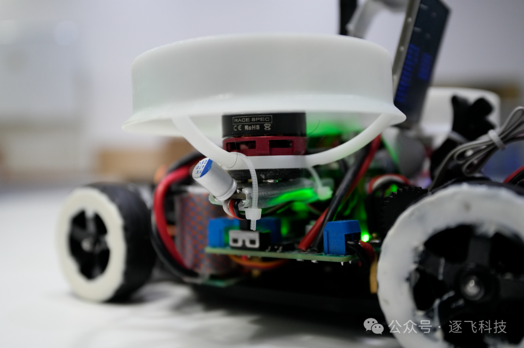
3. Demonstration Car Model
3.1, Basic Line Array CCD Tracking Algorithm Analysis
In the NXP-MicroPython track, the chip provided by NXP supports the 100Pin RT1021, which has sufficient performance. However, the pin resources are somewhat tight. If Python is used to process camera data, the execution efficiency will be lower. Therefore, it is not recommended to use the camera as a tracking sensor. As seen from the demonstration car models of the previous two groups, using line array CCD can achieve tracking effects comparable to that of cameras. Thus, the MicroPython firmware burned into the specified core board is adapted for dual line array CCD modules as a tracking means. Hereinafter, unless otherwise specified, “CCD” refers to the “line array CCD module (Red Boy)”.
We have actually explained the CCD tracking algorithm in previous articles. You can check this article for understanding (although the language is different, the ideas are similar):
Article link:https://mp.weixin.qq.com/s/oFth6JnpLM5PBOfrM25CHA
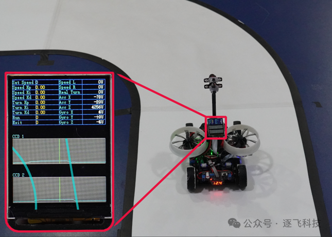
It can be visually seen from the CCD images where the track is located. The image on the straight path appears narrow at the far end and wide at the near end, making it easy to determine that this is a straight path using algorithms when the car body is centered and facing forward:
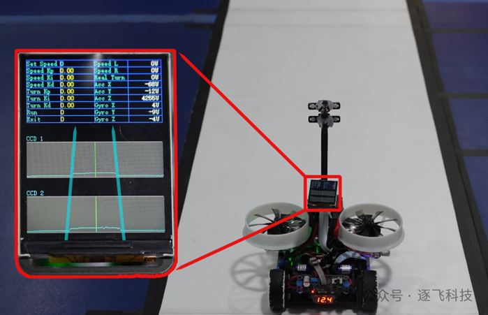
The display effect shown in the image above benefits from Python’s string formatting and the display library provided by NXP. Writing code will no longer require the cumbersome switching between display strings and display function operations as in C language, but will instead directly call the strxx interface to complete the menu display and easily display CCD images on the screen:
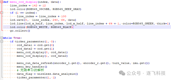
It seems like a lot of work, but using MicroPython only requires a brief reading of the firmware manual, allowing you to write concise Python code and achieve the desired functionality through well-defined interfaces.
When encountering a curve, one can observe that one side becomes wider at the far end in the image. By processing and extracting boundary points, it can be determined that there is a corresponding direction curve ahead (this will involve logic similar to circular processing and requires state judgment):
In fact, another article, “Negative Pressure Lens (STC) Group Analysis of Zhu Fei Demonstration Car Model,” also explains the installation and processing methods for dual CCD:
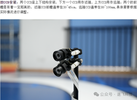
Article link:https://mp.weixin.qq.com/s/oAdXT6ZVaBNCdo5kCCs1_w
3.2, Steering Control Analysis
According to the steering control formula from the previous negative pressure lens demonstration car model:
output=location * KP + abs(location)* location *KP2 +(location - 〖location〗_last ) * KD + groy_z * KD2Slide to view
Compared to the regular PD formula, an additional quadratic term and a differential term have been added. The purpose of adding the quadratic term is to make the car respond more quickly when turning while not being affected on straight paths; the additional differential term uses data from the Z-axis gyroscope, and the effect of adding this is to suppress the steering of the car, aiming to increase steering damping and make the car’s operation more stable.
Notes:
1. To ensure direction consistency, the position deviation in the quadratic term needs to take the absolute value;
2. The quadratic term should not be too large, or it may lead to shaking when taking large arcs;
3. When using gyroscope data as the differential term, pay attention to direction judgment, ensuring that when the vehicle turns right, the servo turns left.
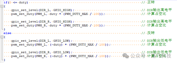
Steering control is not only about controlling the servo, but at a certain speed, the active differential of the rear wheels is also required. Due to the support for driving in the MicroPython firmware, motor control no longer requires attention to driving control as in traditional C programming, but can be flexibly configured for forward and reverse directions, using positive and negative numbers to control the direction:
3.3, Cross and Slope Detection Analysis
As mentioned in previous articles, the CCD only has one line of image information, and the two CCD images indeed lack continuous track information compared to cameras, making it difficult to judge special elements. However, there are still traces to follow:
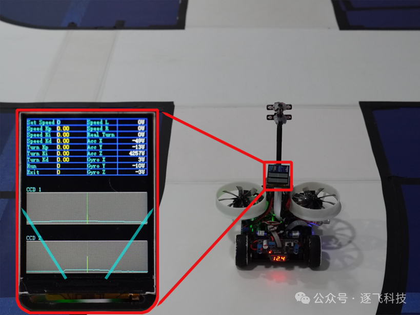
When the car reaches an intersection, both sides will lose the edge line. At this time, we can simply maintain the last turning angle to pass through. However, in actual operation, the car body is mostly not aligned with the intersection, which may cause one side to lose the line first. If only simple steering calculations are performed, the car may turn towards the side that lost the line, thus failing to pass safely. However, software can perform path confidence processing; for curves, one side’s edge line will gradually widen, while at an intersection, it will quickly widen and lose the line. By using historical edge line information, the car’s path can be maintained.
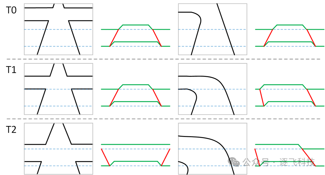
The above diagram shows that the front part on the left quickly loses the line after entering the intersection, while the right side’s curve image gradually moves to the right until it finally loses the line. This situation can be processed through path history to eliminate the sudden loss of line and prevent misjudgment between curves and intersections. In actual control, additional judgment conditions (such as the position deviation of the far-end CCD) can be added to further prevent misjudgment.
As for slope images, the edge line gradually widens. When the car approaches the slope, the CCD boundary information is locally magnified, with data characteristics as shown below:
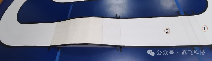
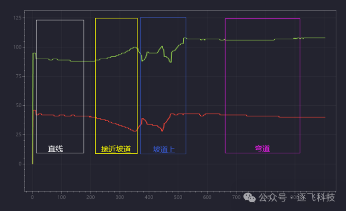
(Through WIRELESS_UART.send_oscilloscope one-click data upload)
We can complete slope detection and control through the following steps:
1. After detecting the slope, perform appropriate deceleration and set the slope flag;
2. When the car goes uphill, if the slope angle is large, the CCD may see the ceiling light or other places, leading to the wrong edge line being searched. Therefore, when extracting edge lines, a certain filtering process needs to be added, and after detecting the slope, a certain angle limit should be set to prevent the car from falling off the slope due to incorrect edge line information;
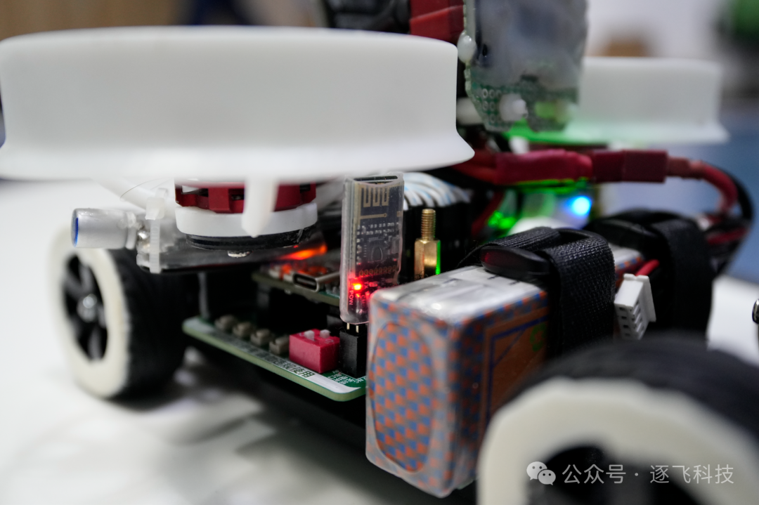
3. The slope can be divided into two sections: uphill and downhill. When the car passes through the slope, the IMU’s acceleration data changes significantly (X-axis or Y-axis, depending on the actual installation situation). The IMU’s acceleration data can be used to judge the car’s position on the slope (the dynamic characteristics of the accelerometer are poor and need to be processed through a first-order low-pass filter before use). When the acceleration data increases (decreases), it indicates that the car is in the uphill phase; when the acceleration data decreases (increases), it indicates that the car is in the downhill phase, allowing for appropriate acceleration. When the acceleration value returns to the value near the car being flat, it indicates that the car has passed the slope, clearing the slope flag and ending the slope control.
3.4 Dual CCD Speed Control Analysis
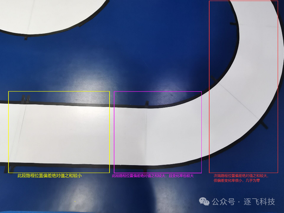
By extracting boundary information from the CCD image, the deviation of the near-end CCD position can be used as a steering basis. Since the far-end CCD has a longer foresight, it can detect curves earlier. Therefore, we can add the absolute values of the deviations from the far-end and near-end CCDs as a basis for deceleration to achieve early deceleration.
We first set a threshold. When the deviation is less than the threshold, it can be considered a straight line and can accelerate. When the deviation exceeds the threshold, it is considered a curve and should decelerate. However, when encountering a large arc or having already entered a curve, it is possible to accelerate appropriately. At this time, we can judge by the rate of change of the sum of the absolute values of the deviations from the two CCDs. When driving in a large arc or within a curve, the rate of change of deviation is very small, nearly zero, allowing for appropriate acceleration.
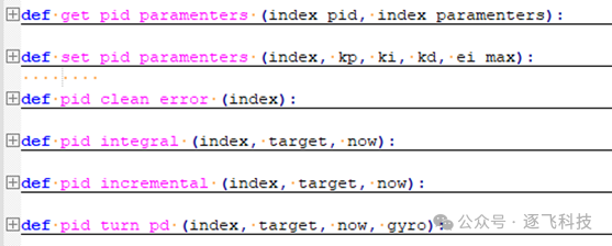
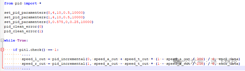
Python also has the advantage of having many open-source algorithms. It can help perform feature extraction by including some image and data processing algorithm libraries, such as the PID algorithm library in Python:
4. Zhu Fei Negative Pressure Lens NXP-MicroPython Track Demonstration Car Model Running Video
From the demonstration car model video, it can be seen that the running effect is basically consistent with directly controlling the car using C language, and the debugging time for this demonstration car model is shorter. If more time is spent on debugging, there will be no difference, indicating that using MicroPython can also allow the car to run at high speed.
5. Recommended Hardware Configuration for Making the Car
5.1 Car Model
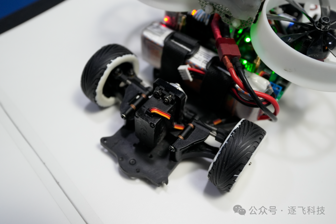
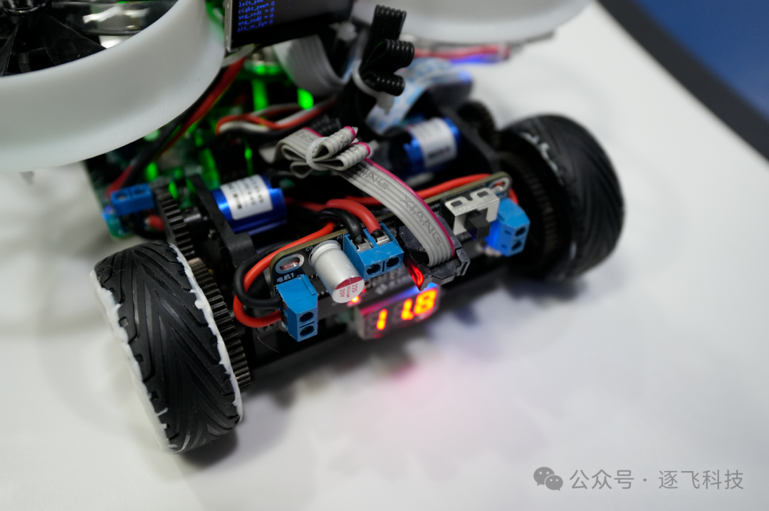
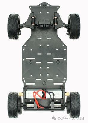
The demonstration car model uses the Zhu Fei mini car model, which has replaced the old 180 motors and servos with new ones.
1. Comparison Test of New and Old 180 Motors
|
Parameter |
New 180 Motor |
Old 180 Motor |
|
Test Voltage |
8V |
8V |
|
No Load Power |
6.4W |
2.8W |
|
No Load Current |
0.80A |
0.35A |
|
No Load Speed |
42817RPM |
17066RPM |
In comparison, the new 180 motor is over twice as fast as the previous 180 motor. However, it should be noted that the rated voltage of the new 180 motor is 8V, so when using a 3S lithium battery to power the drive, be sure to limit the motor output to about 65%; otherwise, it may easily damage the motor.
2. The newly replaced servo has a higher control frequency and response speed and can directly use 2S power supply, but it is not recommended to do so. It is safer to use a separate voltage regulator for power supply.
5.2, Chip Selection
Regarding the chip, the MicroPython competition has already specified the use of designated core boards, which can be applied for special purchase qualifications:
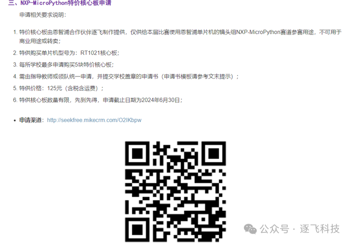
Application link: http://seekfree.mikecrm.com/O2IKbpw
Alternatively, you can also directly purchase the core board at the normal price. The Taobao link is as follows:https://item.taobao.com/item.htm?id=772641532124
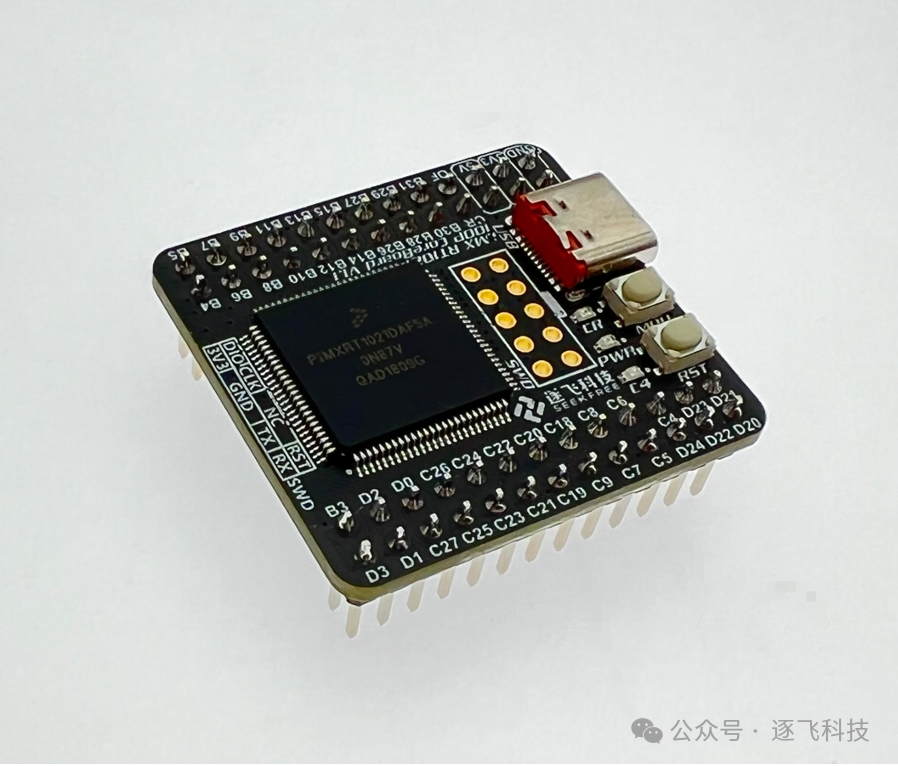
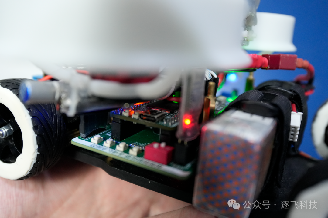
5.3, Main Sensor Selection
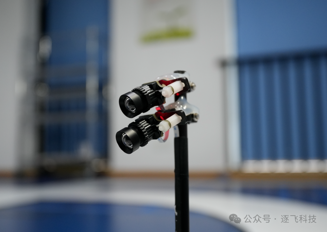
Line Array CCD The demonstration car model uses the Red Boy line array CCD, which has a resolution of 1*128, with stable and convenient data collection. Each car is equipped with two CCDs for easy element recognition.
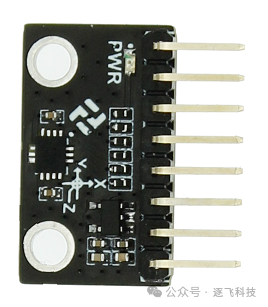
Gyroscope The demonstration car model uses the IMU660RA gyroscope. This is a six-axis gyroscope that we launched, performing better than the ICM20602, with speed and reliability having been tested for a long time. It completely meets competition requirements.
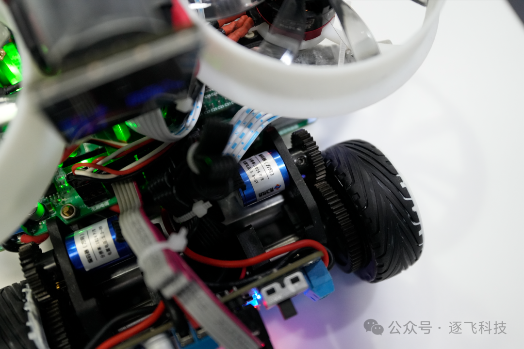
Encoder This time, the car model uses the Zhu Fei mini encoder with direction (Zhu Fei blue encoder).
5.3, Hardware Configuration Table
|
Name |
Quantity |
Description |
|
NXP-MicroPython Track RT1021 Core Board |
1 |
The core board is the designated core board for the NXP-MicroPython track, which can be directly used for competition. Its main function is to ensure the chip works normally and expose all pins, facilitating students’ design of the main control board for use. |
|
NXP MicroPython Track RT1021 Learning Main Board |
1 |
The expansion learning board is used for preliminary training and learning, containing the peripheral interfaces required for the demonstration car model. However, the main control board needed for competition must be designed and produced by the participating students and cannot use a finished expansion learning board for competition. |
|
Red Boy Linear CCD Module |
2 |
It is recommended to use two Red Boy line array CCD modules simultaneously. |
|
Serial IPS200 Screen |
1 |
The NXP MicroPython firmware only supports the SPI interface serial IPS200 screen. |
|
IMU660RA |
1 |
The IMU is an inertial measurement unit. Here we recommend the IMU660RA because this gyroscope uses SPI communication, has a high speed, and can directly use the hardware SPI interface on the STC, serving as steering assistance for the four-wheeled car model. |
|
Encoder (with Direction Output) |
2 |
We recommend using encoders with direction output (Zhu Fei’s blue encoder). |
|
DRV8701E Dual Motor Driver |
1 |
The car has two motors, and here we can choose Zhu Fei’s DRV8701E dual motor driver or the older version of the 4082 driver scheme. The DRV8701E dual motor driver is recommended, as one motor only requires one PWM, making pin allocation more user-friendly. |
|
Brushless Motor, Blades, Protective Cover, Mounting Plate |
2 |
The brushless motor and blades provide negative pressure power for the car, and the carefully designed mounting plate and protective cover can protect the body from being cut by the blades. |
|
STC Electronic Speed Controller |
2 |
The brushless electronic speed controller learning version is used for preliminary learning and scheme verification. For formal competitions, a brushless electronic speed controller must be self-manufactured. |
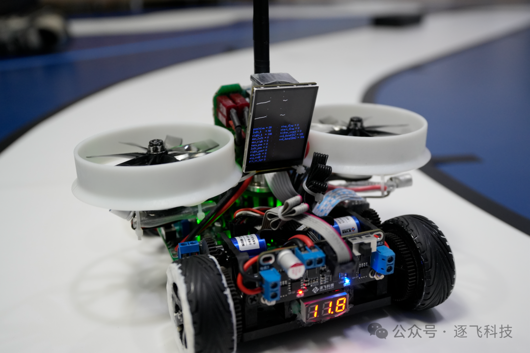
Note: The red-marked RT1021 learning board, driver board, and STC electronic speed controller must be self-designed and manufactured by the participating students.
5.4 Pin Planning Suggestions
We have made resource planning based on the built-in MicroPython resource allocation of the RT1021 core board and the RT1021 main board learning board for everyone’s reference. For details, see the table below:
|
Peripheral Module |
Signal Pin |
Core Board Pin |
|
Wireless to Serial Port |
TXD |
C6 |
|
RXD |
C7 |
|
|
RTS |
D24 |
|
|
Encoder 1 with Direction |
LSB |
D0 |
|
DIR |
D1 |
|
|
Encoder 2 with Direction |
LSB |
D2 |
|
DIR |
D3 |
|
|
SPI Serial IPS200 Screen |
SCK |
B28 |
|
MOSI |
B30 |
|
|
RST |
B9 |
|
|
DC |
B8 |
|
|
CS |
C5 |
|
|
BL |
C4 |
|
|
Attitude Sensor Module |
SCK |
B10 |
|
MOSI |
B12 |
|
|
MISO |
B13 |
|
|
CS |
B11 |
|
|
Motor/DRV8701E |
DIR1 |
C26 |
|
PWM1 |
C24 |
|
|
DIR2 |
C27 |
|
|
PWM2 |
C25 |
|
|
Electronic Speed Controller |
PWM |
B26 |
|
PWM |
B27 |
|
|
Servo |
PWM |
C20 |
|
Button |
IO |
D20 |
|
IO |
D21 |
|
|
IO |
D22 |
|
|
IO |
D23 |
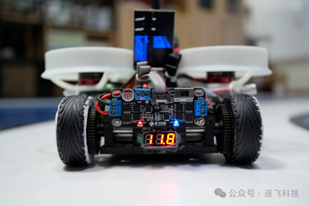
The above are the hardware modules used in the Zhu Fei demonstration car model and the recommended configuration plan for beginners. The designated RT1021 core board, Red Boy line array CCD, wireless to serial port, encoder, IMU660RA, etc., used in this demonstration car model are all on sale. The procurement kits for the camera group NXP-MicroPython track are also available, and students can choose according to their needs.
Zhu Fei Taobao store link: https://seekfree.taobao.com/
Kit link: https://item.taobao.com/item.htm?ft=t&id=662013607337
Special reminder: The core board expansion board (main board), motor driver board, and electronic speed controller required for competition must be self-designed and manufactured by the participating students. The expansion learning boards (main boards), driver boards, and electronic speed controllers sold by Zhu Fei are for reference and learning only and cannot be used directly for competition.
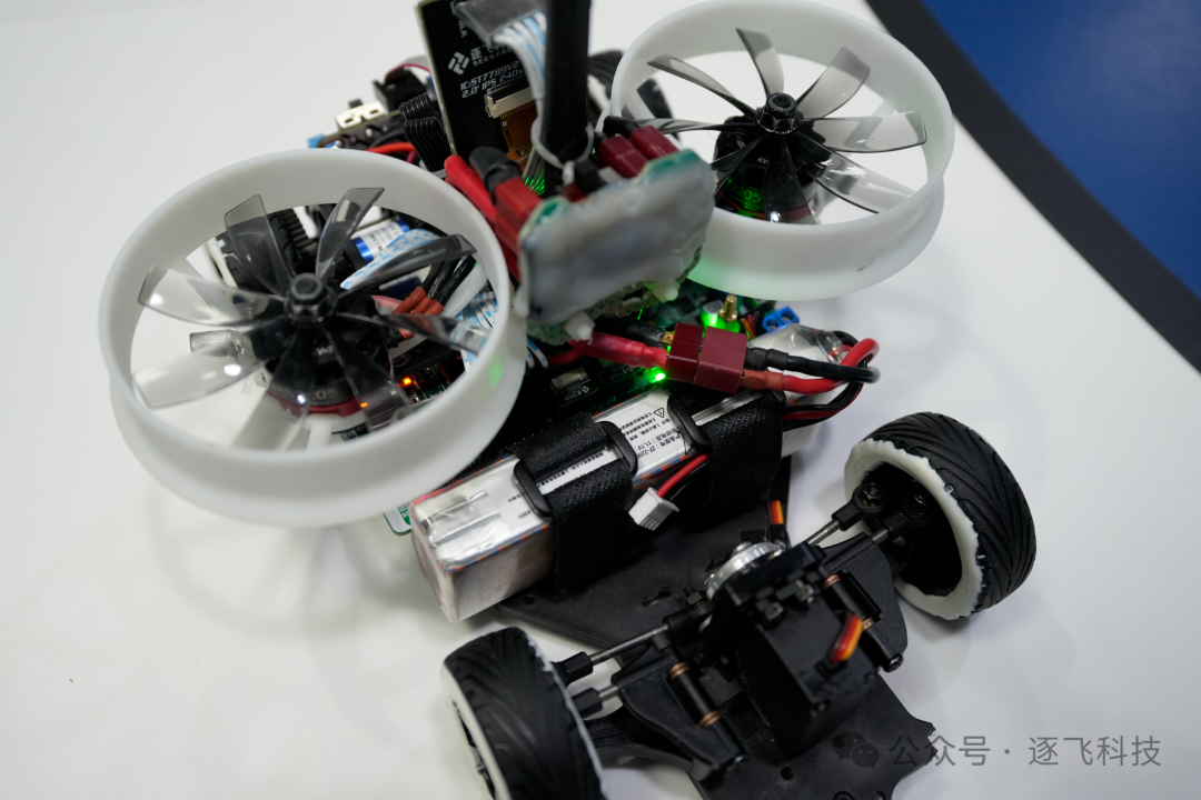
Finally, thank you all for your support. This issue’s introduction to the Zhu Fei demonstration car model in the MicroPython track is coming to an end. The purpose of creating the demonstration car model is to validate the main control MCU chip and MicroPython firmware provided by our partner NXP in conjunction with the competition tasks. It also serves to verify the basic plans we envision and the functionalities of the core boards, sensors, and other products sold. The demonstration car model’s plan may provide some help to beginners, utilizing this opportunity to clarify knowledge applications and provide a basic reference for car model production.All circuit boards’ PCBs and the entire software for the demonstration car model will not be made public, sold, or given away, and are only for sharing validated ideas. These contents are not complicated and are fully aligned with the abilities of university students. If some novice friends are still confused, they can try to create their own cars and write their own codes based on the shared ideas; these are achievable. I hope every participating student can understand not only the “what” but also the “why,” and that by doing things themselves, knowledge truly becomes theirs. Action is the best teacher!
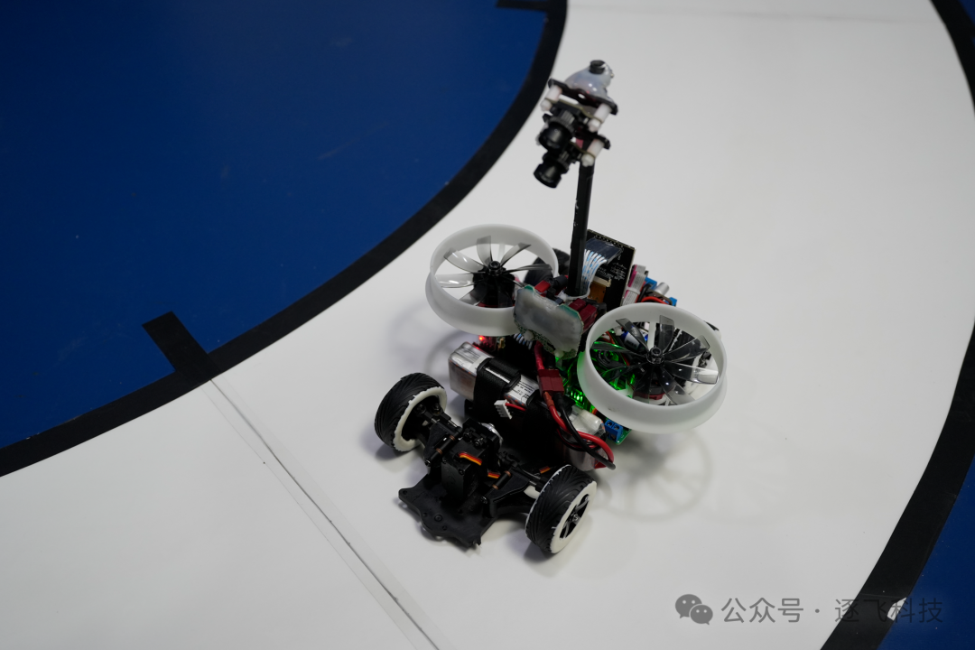
Moreover, our demonstration car model is certainly not the optimal solution. Better methods and algorithms need to be thought out and discovered by car enthusiasts, so that you can become a qualified engineer and possess a skill in the future. The so-called engineering practice activities require you to practice and design and create cars according to competition requirements to gain rewards. Finally, I wish all car enthusiasts to create cars that satisfy them and achieve satisfactory results in the competition while having fun!
Welcome to exchange ideas. We hope that Zhu Fei’s companionship can promote your growth. You can interact through QQ group (Camera Group NXP-MicroPython Track Communication Group – Zhu Fei Technology: 518787217) or leave messages under Zhu Fei Technology’s WeChat public account for communication. We welcome everyone to continue to follow the “Zhu Fei Technology” WeChat public account, where updates on Zhu Fei’s open-source projects, technical sharing, and information related to intelligent vehicle competitions will be published. Click the channel below to follow.