Introduction
PLC (Programmable Logic Controller) was initially just a digital logic controller with a microprocessor for automation control. With the development of programmable logic programs, PLCs have become widely used in the industrial control field, evolving into programmable automation devices similar to compact computers, replacing the numerous relays and counters in automated control systems. PLC control technology has long become an indispensable part of the industry. The compact PLCs produced by Japan’s OMRON Company, as a fully functional compact PLC, have achieved a high market share in China due to their flexible structure, high transmission quality, fast speed, wide range, low cost, and broad applicability. Today we will introduce the proprietary open protocol developed by OMRON – the FINS protocol, which is only supported by the manufacturer’s own devices and provides official documentation.
Introduction to FINS
FINS (Factory Interface Network Service) protocol is a network protocol developed by Japan’s OMRON Company for industrial automation control network command control systems, used for communication between PLCs and computers. By using FINS commands, seamless communication can be achieved among three networks: Ethernet, Controller Link, and RS232C/485 serial communication. The main parameters of these three communication methods are as follows:
Network | RS232C /485 | Controller Link | Ethernet
Transmission Rate | Up to 19.2kb/s | Up to 2MB/S | 10~100MB/s
Transmission Distance | 15m | 500m at maximum transmission rate | 100m/segment
Maximum Number of Nodes | 32 | 32 | 254
From the above data, it is not difficult to see that if we use RS232C/485, its maximum rate of 19.2kb/s can no longer meet the characteristics of modern control systems, which require large amounts of data, long distances, and high real-time requirements.
The design of Controller Link can achieve 2MB/S and a transmission distance of 500m, which is stronger than RS232C/485, but it relies on the installation of a CLK support card on the host computer, so it is less scalable than the Ethernet solution.
Finally, let’s look at the Ethernet solution. The transmission rate of 10~100MB/S can meet the real-time data transmission requirements of modern industry, while the transmission distance of 100m/segment allows for flexible networking, with up to 254 nodes enabling one-to-one, one-to-many, and many-to-many control schemes between PCs and PLCs. Moreover, current industrial equipment’s host computers are equipped with network cards, eliminating the need for additional hardware, providing significant convenience in practical operations. This makes industrial Ethernet meet the demands of good scalability, practicality, and real-time performance. Therefore, OMRON connects client applications, including HMI, SCADA, Historian, MES, ERP, and countless custom applications to controllers by providing the Omron FINS Ethernet driver.
FINS and TCP/IP and UDP/IP Protocols
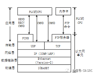
As shown in the figure, during our actual communication process, remote devices use IP addresses at the network layer, the transport layer defines local TCP or UDP port numbers to provide ports for subsequent FINS communication, while the application layer uses the FINS node address (node number). Here, let’s briefly introduce the node number; the concept of a node is similar to the inode in Linux, as a table with a fixed length containing information such as file size and owner. The node number serves as the identity card number for this node, allowing access to the corresponding node content simply by using the node number.
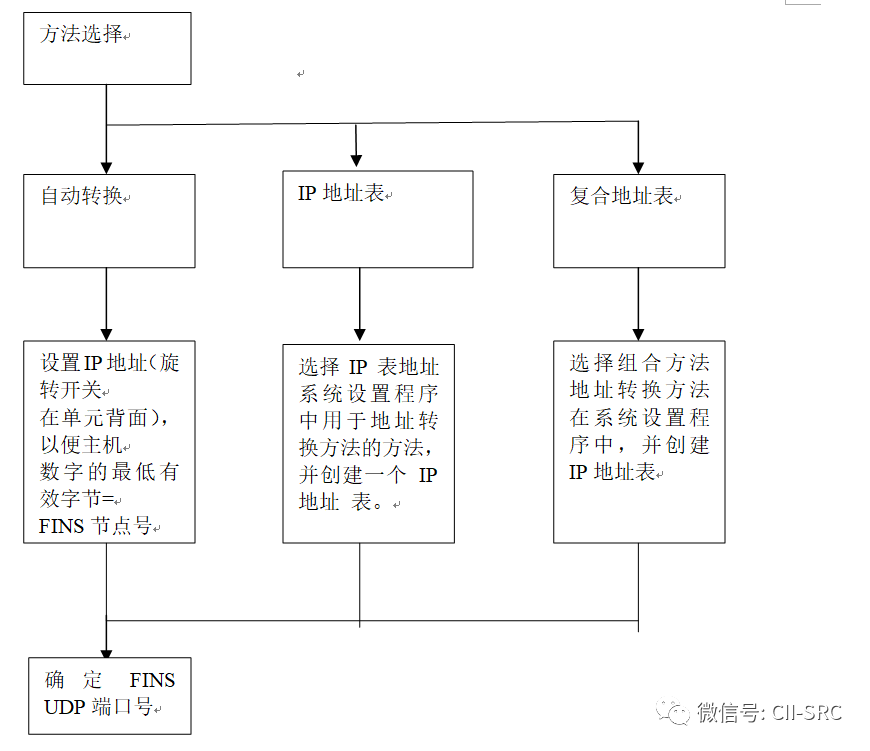
Back to the main topic, during Ethernet communication, we typically use IP addresses, while in FINS communication, we use network numbers, node numbers, and unit numbers to correspond to different devices. Using node numbers allows devices to convert between IP addresses and node numbers. The node number provides a unified addressing method between Control Link networks and Ethernet, enabling devices across different networks to communicate uniformly. Devices can convert between node numbers and IP addresses through three methods: automatic conversion, IP address tables, and combined address tables. Determining which conversion method to use is the first step we need to take when using FINS. Next, let’s briefly discuss the differences between these three methods.
Automatic Conversion: As the name suggests, automatic conversion to FINS node numbers.
IP Address Table: Converted from the correspondence table between INS nodes and IP addresses.
Combined Address Table: References the IP address table; if the IP address is not registered, it will then convert from FINS to node numbers.
See the diagram below for details.
Generally speaking, the default port number for FINS is 9600; if it is not, you need to set the port number yourself. In any case, all Ethernet units must be set to the same value.
In general, we consider FINS frames to belong to the link layer. All OMRON products support FINS/UDP transmission, which has a faster transmission speed because UDP is a connectionless protocol. When transmitting between two nodes, there is no explicit connection relationship between the nodes. Another method is FINS/TCP, which is suitable for CS1W-ETN21 and CJ1W-ETN21. We utilize TCP/IP protocol for transmission by treating FINS as the data area of UDP. The advantage of this method is its high reliability.
Analysis of FINS Frame Format
FINS communication is conducted through the exchange of FINS command frames and their response frames (some may not have responses). Both command and response frames consist of the FINS header, which stores transmission control information, and stores command and response information separately.
Next, let’s look at the command frame and response frame.
Command Frame
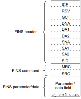
First, let’s look at the composition of the command frame, as shown in the figure below.
Next, let’s analyze each part briefly.
FINS header:
ICF: 1 byte, used to display frame information.
RSV: 1 byte, reserved by the system, set to 00 (hexadecimal).
GCT: 1 byte, number of gateways allowed, set to 02 (hexadecimal).
DNA: 1 byte, destination network address, used to specify the target node’s network number, 0 for local, 01~7F for target networks.
DA1: 1 byte, destination node address, specifies the node number to send the command to, 00 for local, 01~7E for target node numbers, FF for broadcast number when multiple network units are installed.
DA2: 1 byte, destination unit address, specifies the target node’s unit number, 00 for local, 10~1F for CPU bus units, E1 for internal boards, FE for networked.
SNA: 1 byte, source network address, specifies the source node’s network number, 00 for local, 01~7F for network numbers.
SA1: 1 byte, source node address, same as above.
SA2: 1 byte, source unit address, same as above.
SID: 1 byte, service number, identifies the generated transmission process, set to a number from 00 to FF, the same number is returned in the response to match the command and response.
FINS command:
MRC: 1 byte, main request code.
SRC: 1 byte, sub-request code.
FINS parameter/data
data field: maximum 2000 bytes, command parameters and data, length depends on MRC and SRC.
Response Frame
Let’s first look at the composition diagram.
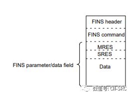
We can see that the difference between the command frame and the response frame is minimal, focusing on the part below FINS command. Let’s take a look.
MRES: 1 byte, main response code.
SRES: 1 byte, sub-response code.
Data: maximum 1998 bytes, some data lengths may be 0.
Why is the maximum value of the response frame less than that of the command frame by two bytes? The reason lies in the fact that the MRES, SRES, and data of the response frame together form the FINS data domain, while the FINS data domain of the command frame is solely composed of the Data value.
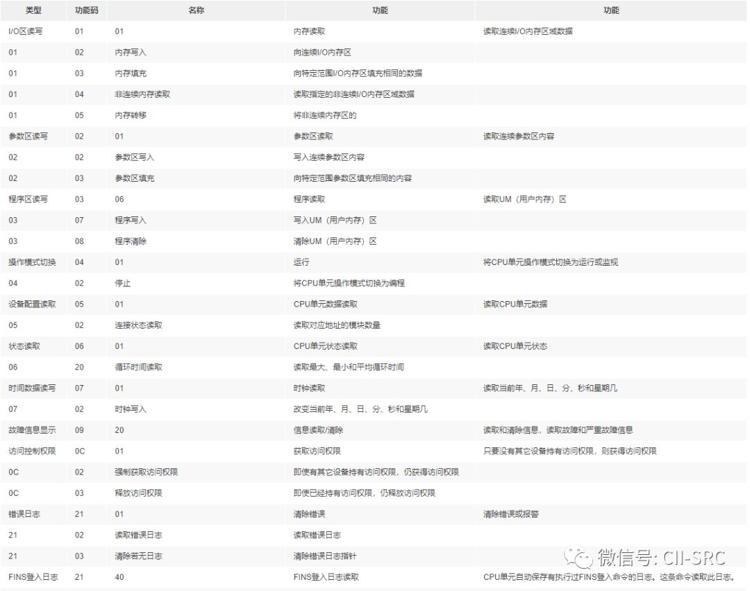
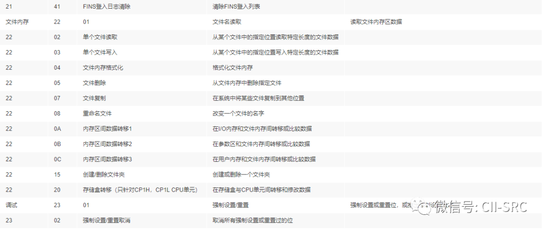
Below is the FINS function codes I found for your reference.
Analysis of FINS Data Packets
The basic knowledge and composition of the FINS protocol have been introduced. Now, let’s analyze the FINS data packet.
We look at this data packet, which is composed of multiple FINS commands.
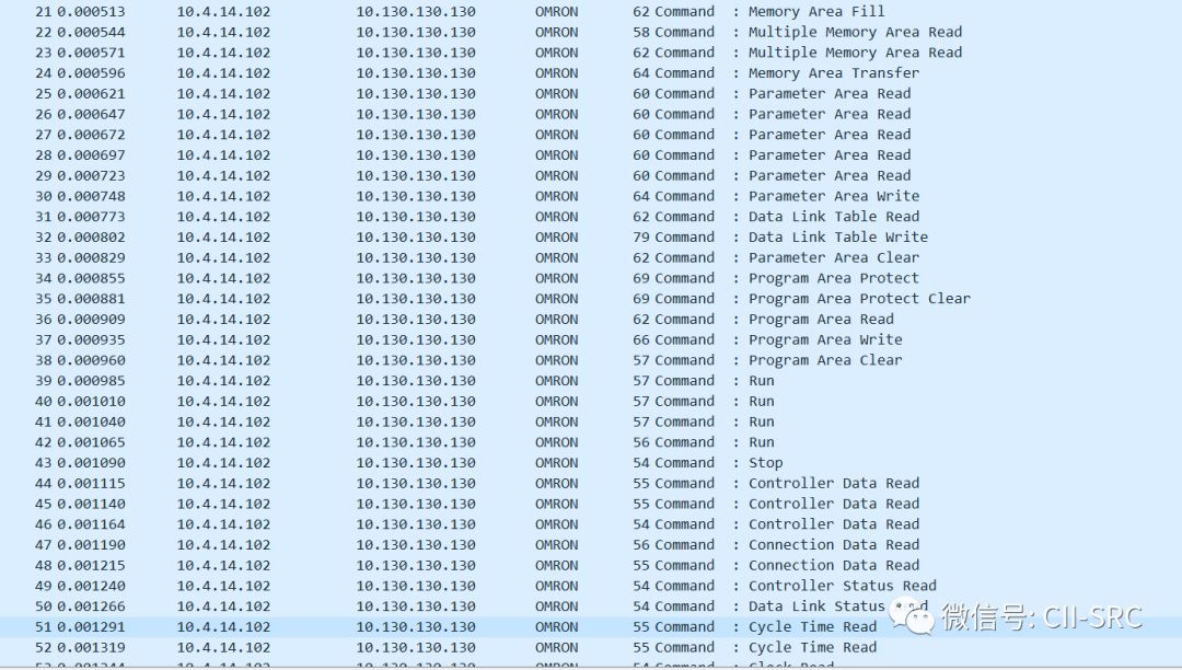
We randomly open several data packets and find that their composition is the same except for the Command code and Data part. Next, let’s take a closer look.
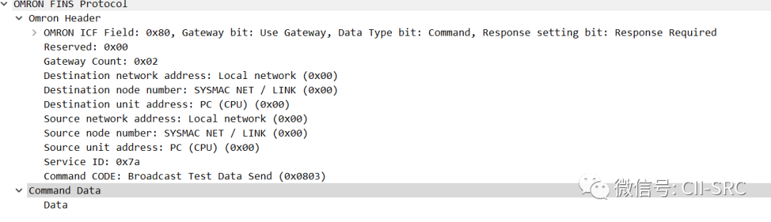
Omron Header
Let’s analyze step by step from the top.
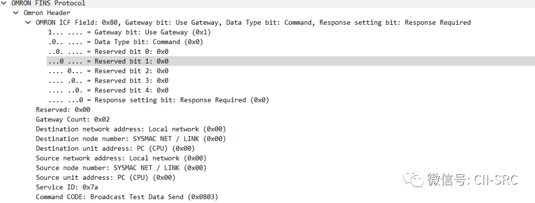
OMRON ICF Field: We have already introduced the role of ICF, which provides frame information. This occupies only one byte (80), but contains the gateway bit, data type bit, and response setting bit.
1 … …. = Gateway bit: Use gateway (0x01).
0 .. …. = Data type bit: No response (0x00).
.0. … = Reserved bit 0: 0x00.
..0 …. = Reserved bit 1: 0x00.
… 0 … = Reserved bit 2: 0x00.
…. 0 .. = Reserved bit 3: 0x00.
….. 0 = Reserved bit 4: 0x00.
… … 0 = Response setting bit: Requires response (0x00).
The first 1 indicates that the gateway bit is used (0x01), the following 0 indicates that the data type bit does not respond, followed by five reserved bits, and the last bit 0 indicates that the response is set to require a response.
The reserved bits can perform the following:
0x00 Gateway Count: 0x02 Destination Network Address: Local Network (0x00) Destination Node Number: SYSMAC NET / LINK (0x00) Destination Unit Address:
PC (CPU) (0x00) Source Network Address: Local Network (0x00) Source Node Number: SYSMAC NET / LINK (0x00) Source Unit Address: PC (CPU) (0x00) Service Number: 0x7a Command Code: Name Delete (0x2602).
Next, Reserved and Gateway Count are both fixed reserved bits, so I won’t elaborate further.
Destination Network Address: The following is the Local Network, representing the local network, as mentioned earlier, here changes in different networks.
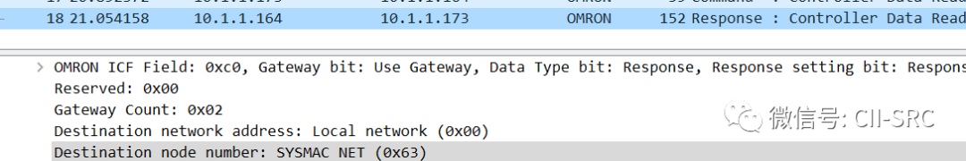
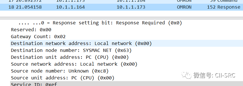
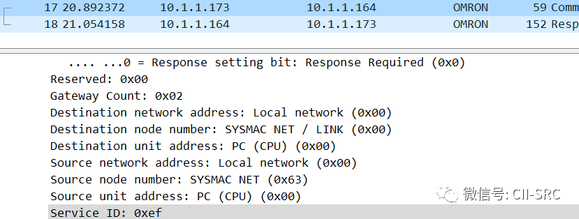
Destination Node Number: The target node number, SYSMAC NET/LINK represents the fiber optic network, using distributed control SYMAC LINK medium network. Here, when marking the command frame, it indicates SYSMAC NET/LINK (0x00), but in the response frame, it is SYSMAC NET (0x63). However, in another data packet, the content of the response frame is the same as that of the command frame. I have not found an answer to this; if anyone knows, I hope they can explain.
Destination Unit Address: The destination unit address, since this is a local simulation experiment, all addresses are PC (CPU).
Service ID: The service identifier generated by the command frame, which is returned with the same value in the response frame.
Finally, the Command CODE is the most critical content of the command and response packet, containing the content and command code.
Command Data
This part is straightforward; it is the content of the command or response.
Security Status
According to a scan by Lighthouse Lab in 2015 of global OMRON devices, the most exposed networks are in the USA, Italy, Spain, France, and other countries, with most located in Europe and the USA. However, Japan, where OMRON is located, has relatively few exposures. Once the ports of such PLCs are exposed on the public internet, devices can be operated directly through software or protocols. Therefore, it is recommended to set passwords and establish firewalls in actual configurations.
In 2015, the FINS protocol exposed the misuse of PLC’s forced function (forced setting of memory variables that are unaffected by the program, remaining unchanged under user logic program control) to control PLC devices. As of July 2019, OMRON devices ranked fifth in exposure nationwide, with three high-risk vulnerabilities found in CP1 model devices, making PLC security issues urgent. Recommendations include physical isolation, enhanced log monitoring, increased security assessments and penetration testing, and adopting more secure operating systems to strengthen PLC security control.
Original source: Security Guest