
-
After writing the letter, I will write my friend A’s address on it and drop it off at the Beijing post office (attach the target IP address to the information and send it to the router). -
The post office will help me transport the letter to the local post office in Shanghai (the information will be routed to the router of the target IP local area network). -
The local router in Shanghai will help me deliver the letter to my friend A (communication within the local area network).

-
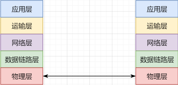
The lowest level is the physical layer, responsible for direct communication between two machines through hardware; -
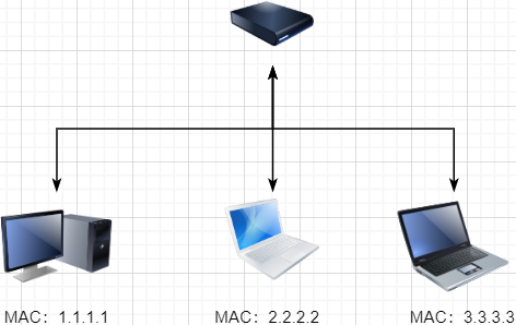
The data link layer uses hardware addresses for addressing within the local area network, achieving local area network communication; -
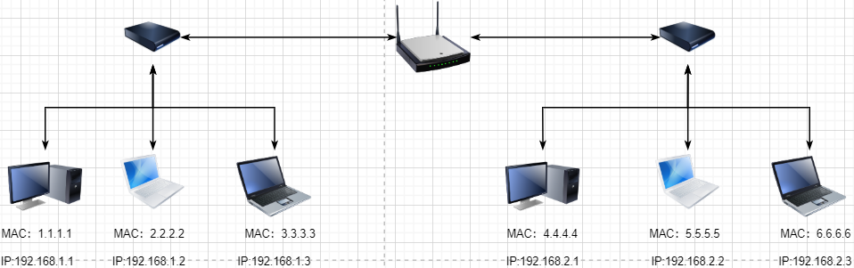
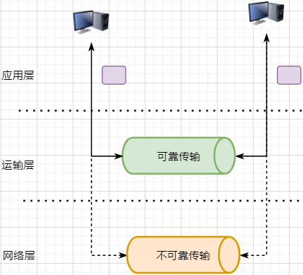
The network layer achieves logical communication between hosts through abstracting IP addresses; -
The transport layer, based on the network layer, splits data to achieve independent network communication for application processes; -
The application layer, based on the transport layer, develops various functions based on specific requirements.
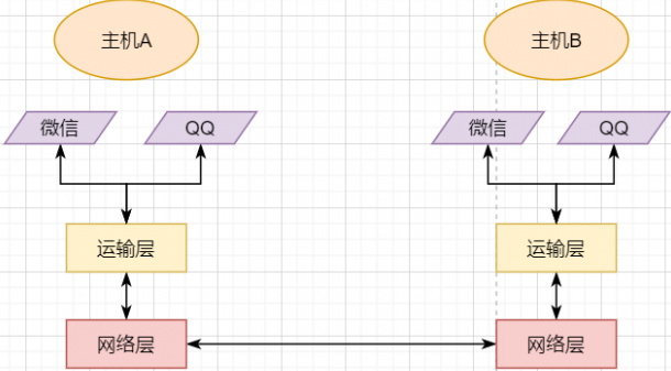
Essence: Provide Process Communication
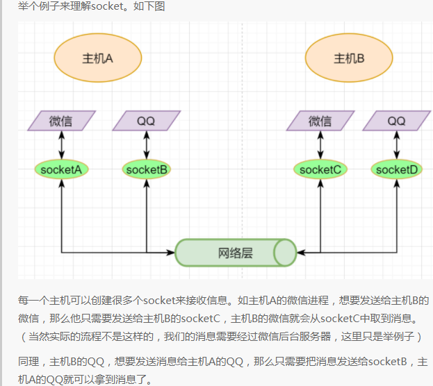
Underlying Implementation: Socket
Transport Layer Protocols
-
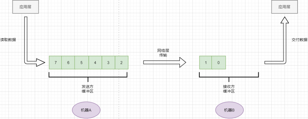
TCP reads data from the application layer in a stream format and stores it in its sending buffer while numbering these bytes. -
TCP selects an appropriate amount of bytes from the sending buffer to form a TCP message, sending it through the network layer to the target. -
The target reads the bytes and stores them in its receiving buffer, delivering them to the application layer at the appropriate time.
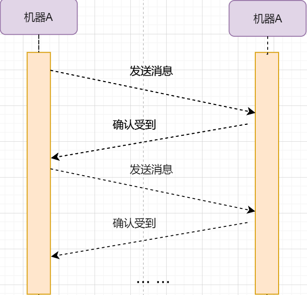
Stop-and-Wait Protocol
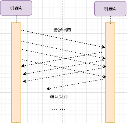
Continuous ARQ Protocol
-
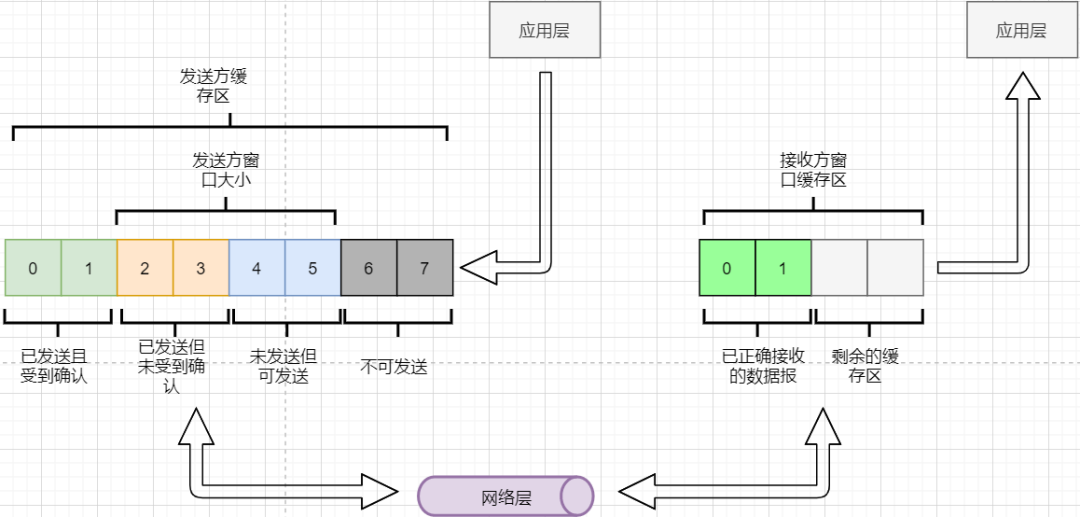
The sender must set its own send window size based on the receiver’s buffer size; data within the window can be sent, while data outside cannot. -
When the data within the window receives an acknowledgment reply, the entire window moves forward until all data is sent.
Summary of Reliable Transmission
-
Through the continuous ARQ protocol and the send-acknowledgment reply model, ensure that each data packet reaches the receiver. -
By numbering bytes, mark whether each data packet is new or a retransmission. -
Utilize timeout retransmission to address packet loss in the network. -
Implement flow control through the sliding window. -
Enhance acknowledgment and retransmission efficiency through cumulative acknowledgment and selective acknowledgment.
-
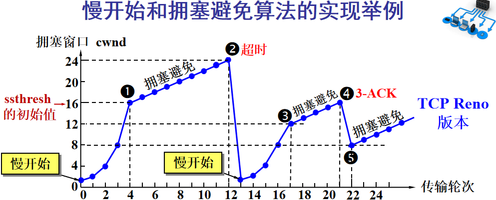
Initially, the window is set to a small value, then doubles with each round. This is the slow start. -
When the window value reaches the ssthresh value, which is a window limit that needs to be set based on real-time network conditions, it enters congestion avoidance, increasing the window value by 1 each round to gradually probe the network’s limits. -
If data times out, it indicates a high likelihood of congestion, and the process returns to slow start, repeating the previous steps. -
If three identical acknowledgment replies are received, it indicates that the network condition is not good; the ssthresh value is set to half of its original value, continuing with congestion avoidance. This part is called fast recovery. -
If packet loss information is received, the lost packets should be retransmitted promptly; this is fast retransmission. -
Of course, the upper limit of the window cannot increase indefinitely; it cannot exceed the size of the receiver’s buffer.
If TCP were to define sockets using only the target IP and target port number like UDP, multiple senders could simultaneously send to the same target socket. In this case, TCP would not be able to distinguish whether the data came from different senders, leading to errors.
Establishing a Connection
-
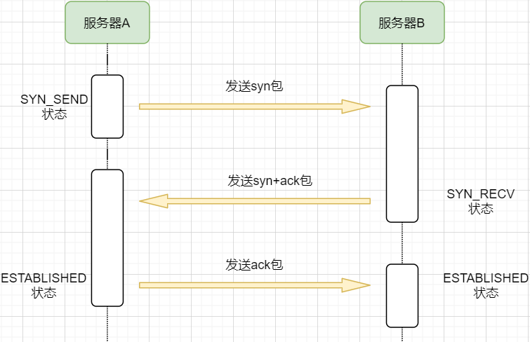
Machine A sends a SYN packet to machine B requesting to establish a TCP connection, attaching its receiving buffer information, etc.; machine A enters the SYN_SEND state, indicating that the request has been sent and is waiting for a reply. -
Machine B receives the request, records machine A’s information, creates its own receiving buffer, and sends a combined SYN+ACK packet back to machine A, while entering the SYN_RECV state, indicating that it is ready and waiting for machine A’s reply to send data to A. -
Machine A receives the reply, records machine B’s information, sends an ACK message, and enters the ESTABLISHED state, indicating that it is fully prepared to send and receive. -
Machine B receives the ACK data and enters the ESTABLISHED state.
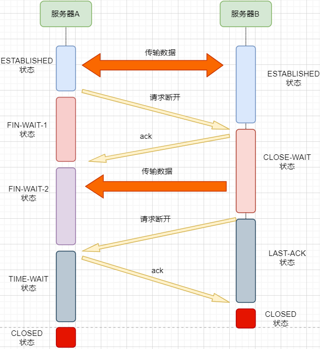
Disconnecting a Connection
-
We know that the network is unstable; machine B may have sent some data that has not yet arrived (slower than the FIN packet); -
At the same time, the replying ACK packet may be lost, and machine B will retransmit the FIN packet;
-
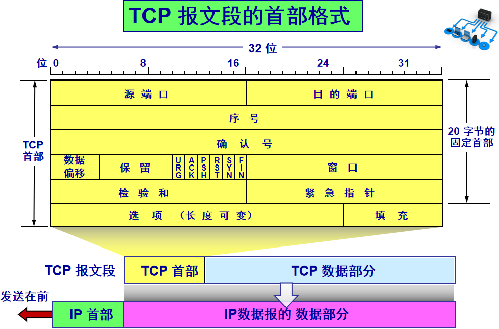
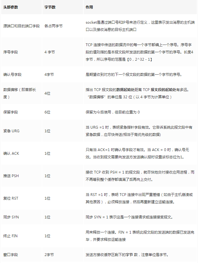
Source port, destination port: port numbers used to distinguish different processes on the host. -
Checksum: used to verify that the data packet has not been corrupted during transmission, for example, if a 1 has become a 0. -
Length: the length of the message.
Disadvantages of UDP
-
Cannot guarantee that messages are complete or arrive correctly; UDP is an unreliable transport protocol; -
Lacks congestion control, which can lead to resource competition and network system crashes.
Advantages of UDP
-
Faster efficiency; no need to establish connections or control congestion. -
Can connect to more clients; no connection state, no need to create buffers for each client, etc. -
Smaller packet header size, leading to lower overhead; the fixed header size of TCP is 20 bytes, while UDP is only 8 bytes; a smaller header means a larger proportion of data. -
In scenarios where high efficiency is needed and some error allowance is acceptable, it can be used. For example, in live broadcasting, it is not necessary for every data packet to arrive intact, and a certain packet loss rate is acceptable. In this case, TCP’s reliable features become a burden; the streamlined UDP is a more suitable choice for higher efficiency. -
Can perform broadcasting; UDP is not connection-oriented, so it can send messages to multiple processes simultaneously.
Applicable Scenarios for UDP
-
Video live streaming. -
DNS. -
RIP routing protocol.
Chunked Transfer
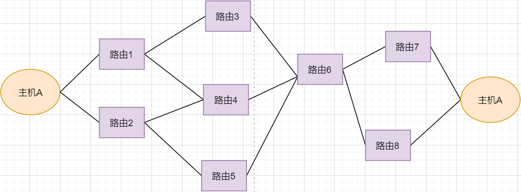
Routing Conversion
-
Under normal circumstances, the data packet from host A can be transmitted via paths 1-3-6-7. -
If router 3 breaks down, it can be transmitted via 1-4-6-7. -
If router 4 also breaks down, it can only be transmitted via 2-5-6-7. -
If router 5 breaks down, the connection will be interrupted.
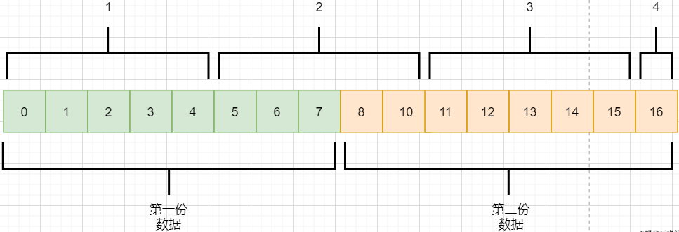
Packet Sticking and Unpacking
-
The application layer needs to send two pieces of data to the target process: one audio and one text. -
TCP only knows that it has received a stream and splits it into four segments for sending. -
The data in the second packet may contain mixed data from both files, which is called packet sticking. -
The application layer of the target process needs to unpack this data to separate the two files correctly, which is called unpacking.
Malicious Attacks
Long Connections
Source: https://juejin.cn/user/3931509313252552/posts