“Assembly Language”, 3rd Edition by Wang Shuang
Chapter 9: Principles of Transfer Instructions
Experiment 9 Programming based on the materials (Page 187)
This programming task must be completed independently before proceeding with the following courses, as the programming experience gained from this experiment will be required in subsequent lessons.
Programming: Display the strings ‘welcome to masm!’ in green, green background with red text, and white background with blue text in the center of the screen.
The knowledge required for programming is obtained by reading and analyzing the materials below.
Structure of the 80×25 Color Character Mode Display Buffer (hereinafter referred to as the display buffer):
In the memory address space, the range B8000H~BFFFFH occupies a total of 32K space, which is the display buffer for the 80×25 color character mode. Writing data to this address space will immediately display the content on the monitor.
In the 80×25 color character mode, the monitor can display 25 lines, with 80 characters per line, and each character can have 256 attribute combinations (background color, foreground color, blinking, highlighting, etc.). Thus, each character occupies two bytes in the display buffer, storing the ASCII code and the attribute. In 80×25 mode, the content of one screen occupies a total of 4000 bytes in the display buffer.
The display buffer is divided into 8 pages, each page being 4KB (≈4000B), and the monitor can display the content of any page. Generally, the content of page 0 is displayed. This means that typically, the 4000 bytes of content from 8000H~B8F9FH will appear on the monitor.
In one page of the display buffer:
Offset 000~09F corresponds to the first line on the monitor (80 characters occupy 160 bytes);
Offset 0A0~13F corresponds to the second line;
Offset 140~1DF corresponds to the third line;
And so on, it can be seen that offset F00~F9F corresponds to the 25th line on the monitor.
In one line, a character occupies two bytes of storage space (one word), with the low byte storing the ASCII code of the character and the high byte storing the character’s attribute. A line contains 80 characters, occupying 160 bytes.
That is, in one line:
00~01 unit corresponds to the first column on the monitor;
02~03 unit corresponds to the second column;
04~05 unit corresponds to the third column;
And so on, it can be seen that 9E~9F units correspond to the 80th column on the monitor.
Example: Display the string ‘ABCDEF’ with a black background and green text at row 0, column 0 on the monitor (the ASCII code for ‘A’ is 41H, and 02H represents black background with green text).
The content in the display buffer is:

It can be seen that in the display buffer, even addresses store characters, while odd addresses store the color attributes of the characters.
A character displayed on the screen has two colors: foreground (character color) and background (background color), and the character can also be displayed in high brightness and blinking modes. The foreground color, background color, blinking, highlighting, and other information are recorded in the attribute byte.
Format of the attribute byte:

R: Red G: Green B: Blue
Attributes can be set bitwise in the attribute byte to create various foreground and background colors. For example:
Red background with green text, attribute byte: 01000010B;
Red background with blinking green text, attribute byte: 11000010B;
Red background with highlighted green text, attribute byte: 01001010B;
Black background with white text, attribute byte: 00000111B;
White background with blue text, attribute byte: 01110001B;
Example: Display the string ‘ABCDEF’ with a red background, highlighted, and blinking green text at row 0, column 0 on the monitor (red background, highlighted, blinking green, attribute byte: 11001010B, which is CAH).
The content in the display buffer is:

Note that the blinking effect can only be seen in full-screen DOS mode.
===================
This experiment is not difficult; it simply involves using loops to write data to the video memory area.
Reference code implementation is as follows:
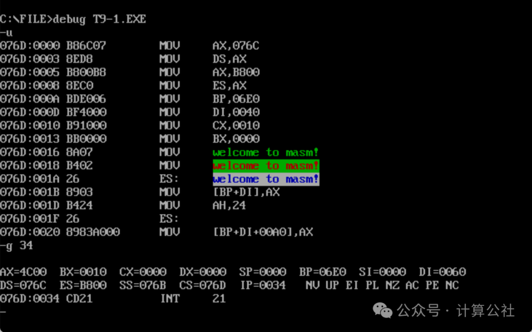
;"Assembly Language", 3rd Edition by Wang Shuang; Chapter 9: Principles of Transfer Instructions; Experiment 9: Programming based on the materials (Page 187)assume cs:code, ds:data data segment db 'welcome to masm!'data endscode segment start: mov ax, data mov ds, ax mov ax, 0B800H ; cannot start with a letter, so add 0 before B8 mov es, ax ; cannot directly write data to segment registers like ds, es mov bp, 160*11 ; starting line, index for the 12th line is 11 mov di, 64 ; starting column mov cx, 16 mov bx, 0 s: mov al, [bx] mov ah, 02H ;(black background) green text mov es:[bp+di], ax mov ah, 24H ; green background red text mov es:[bp+160+di], ax mov ah, 71H ; white background blue text mov es:[bp+320+di], ax inc bx add di, 2 loop s mov ax, 4c00H int 21Hcode endsend start
The code compiled and tested successfully, as shown in the image below: