For more details, please visit www.cpcashow.com

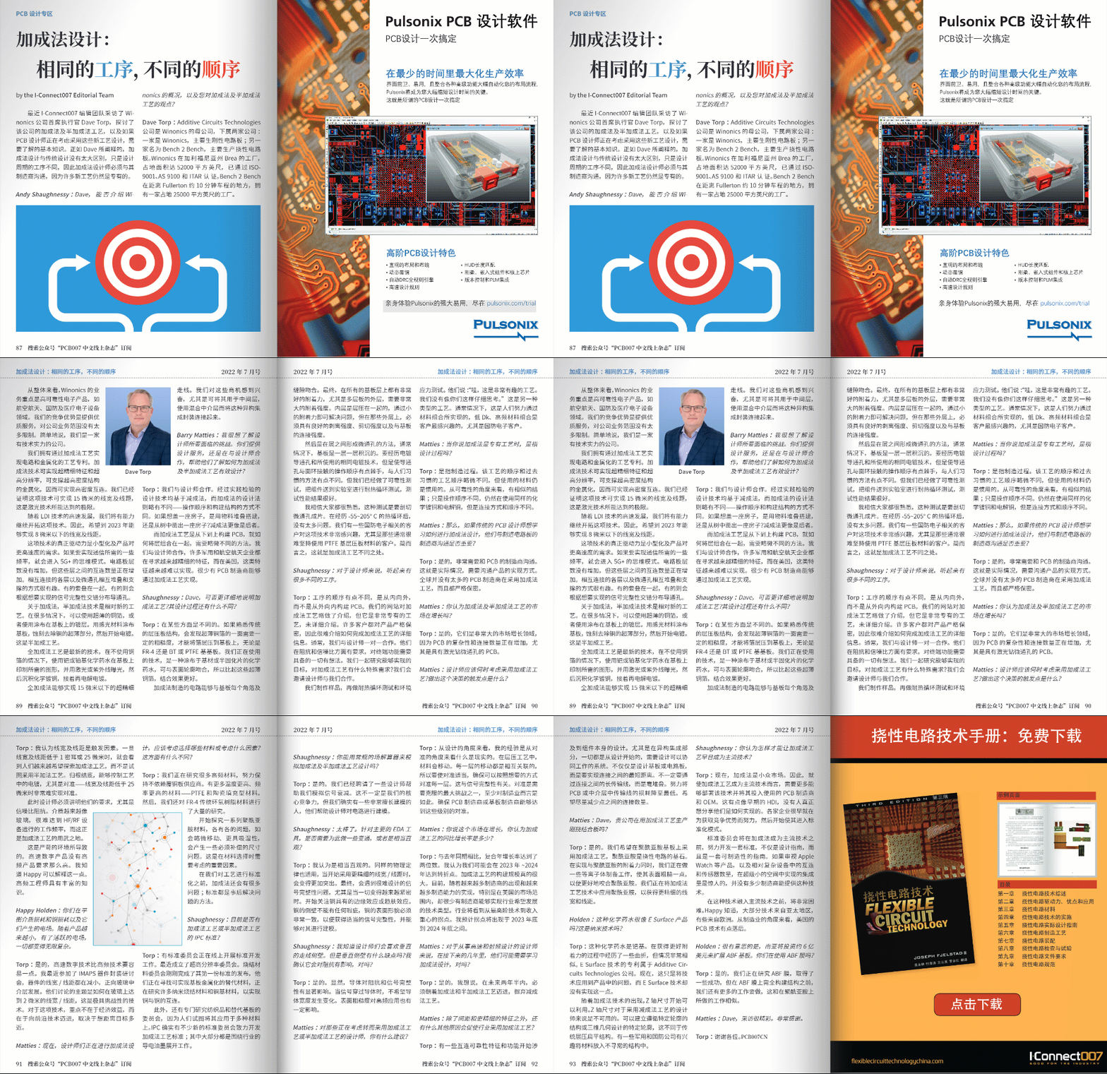
Recently, the I-Connect007 editorial team interviewed Dave Torp, CEO of Winonics, discussing the company’s additive and semi-additive processes, as well as the basic knowledge PCB designers need to consider when adopting these new processes. As Dave explained, additive design is not much different from traditional design; it is just the sequence of processes in the design cycle that varies. Therefore, additive designers must communicate with their manufacturers, as many new processes are still proprietary.
Andy Shaughnessy: Dave, could you introduce Winonics and share your views on the additive and semi-additive processes?
Dave Torp: Additive Circuits Technologies is the parent company of Winonics, which has two subsidiaries: one is Winonics, mainly producing rigid circuit boards; the other is Bench 2 Bench, primarily focused on flexible circuit boards. Winonics’s factory in Brea, California, covers 52,000 square feet and has obtained ISO-9001, AS 9100, and ITAR certifications. Bench 2 Bench has a 25,000 square foot facility located about 10 minutes from Fullerton.
Overall, Winonics focuses on high-reliability electronic products in sectors like aerospace, defense, and medical electronics. Our competitive advantage lies in providing quality service without too many restrictions on the scope of our business. Simply put, we are a company with technical strength.
We hold patents for processes that achieve circuits and metallization through additive methods. Additive technology enables ultra-fine features and ultra-high resolution, supporting metallization of ultra-high density structures, thereby achieving high-density interconnects. We have demonstrated that this technology can achieve a line width and spacing of 15 microns, which is the limit of laser technology.
With the rapid development of LDI technology, we will continue to expand this technology. Therefore, we hope to achieve line widths and spacings below 8 microns by 2023.
The real driving force behind this technology is miniaturization and the demand for higher speeds in products. To achieve certain frequencies required for communication, we enter the 5G+ mindset. The number of interconnections between layers has increased without adding layers to the circuit board. The way the interconnected layers and microvias stack and support each other is intriguing. Some must be stacked together, while others will be distributed interleaved based on the desired signal integrity.
Regarding additive methods, semi-additive technology is a relatively new process. In many cases, ultra-thin copper foil can be used, or coatings applied to the substrate. A photosensitive material is applied to the substrate, and the ultra-thin parts of the copper are etched away, followed by electroplating. This is the semi-additive process.
The full additive process is the latest technology, which prints the desired patterns on the substrate using palladium or platinum-based chemicals without using copper foil. It is then exposed with lasers or ultraviolet light, followed by depositing chemical copper plating, and then electroplating.
Full additive processes can achieve ultra-fine traces below 15 microns. We are excited about these business opportunities, especially as they can be used in intermediate layers, connecting heterogeneous integrated packaging with mixed intermediate layers.
Barry Matties: I would like to understand the challenges designers face. Do you provide design services, or do you work with designers to help them understand how to effectively design for additive and semi-additive processes?
Torp: We collaborate with designers. The design techniques that have been validated through practice are based on subtractive methods, while the design rules for additive methods are slightly different; the sequence of operations and the way structures are built differ. If you want to build a house, do you stack materials or carve a house out of a tree? Subtractive methods are more like the latter.
Additive processes build PCBs from the bottom up, requiring a slightly different approach to how layers are combined. We work with designers, as many military and aerospace companies are seeking increasingly fine features, which are becoming more challenging to achieve in the U.S. Very few PCB manufacturers can achieve this through additive processes.
Shaughnessy: Dave, could you elaborate on the additive process? What differences exist in the design process?
Torp: In some ways, it is different. If you are familiar with traditional laminate structures, you will find that one side of the ultra-thin copper foil needs a certain roughness to laminate the foil to the substrate, whether it is FR-4, BT, or PTFE substrates. The technology we are using is a chemical solution applied to the substrate or prepreg that matches the surface profile, providing better adhesion than these ultra-thin copper foils.
Circuits manufactured through additive methods can conform to every corner and gap of the substrate. Ultimately, there is very good adhesion across all substrate layers, especially for outer layers of multilayer boards, which require very high adhesion strength. The inner layers are laminated together, and a small adhesion strength suffices, but for those outer layers, good peel strength, shear strength, and bonding strength with the substrate are essential.
Then there is the method of forming microvias between layers, which usually involves layering the substrate. The same plating technology used for the vias is applied, but the sequence of operations to make the vias contact the surface rings is a bit tricky and differs from the conventional methods. However, we have conducted reliability tests, sending components to the lab for thermal cycling tests, and the performance results are excellent.
I believe everyone is familiar with this testing, which involves slicing microvias into sections. After undergoing thermal cycling from -55 to 205°C, there are not many issues. We have some defense electronics clients very interested in this technology, especially those who typically find it challenging to stick with PTFE-based laminate materials. In short, this is the difference in additive processes.
Shaughnessy: It sounds like there are many different processes for designers.
Torp: The order of the processes is a bit different; it builds the PCB from the inside out rather than outside in. Our website provides a brief introduction to the additive process, but it is a very proprietary process and does not go into detail. Many clients maintain strict confidentiality regarding their products, making it difficult to provide detailed information on how the additive process is completed. Typically, we work one-on-one with designers. They have requirements for impedance and signal-to-noise ratios and ideas about everything the end product must achieve. We explore achievable goals together and discuss any specific requirements for the additive process. We invite designers to collaborate with us.
We create samples, then conduct thermal cycling tests and environmental stress tests. They say, “Wow, this is a very interesting process. We haven’t thought through it as carefully as you have.” This represents a different type of process. Generally, it is something people strive to achieve through material combinations, and low Dk, high-frequency material combinations are of high interest to clients, especially in defense electronics.
Matties: When you say additive methods are proprietary, do you mean the design process?
Torp: It refers to the manufacturing process. The sequence of this process is slightly different from the conventional sequence, but the materials used remain standard. From a reliability perspective, the results are similar; it is just the operational sequence that differs. We still use the same chemical copper plating and electrolytic copper, but the way they connect and the sequence differ.
Matties: So, if traditional PCB designers want to learn how to do additive design, is it important for them to communicate with the manufacturers of circuit boards?
Torp: Yes, it is crucial to communicate with the PCB manufacturer. That is the reality; communication about how the product will be realized is necessary. There are not many PCB manufacturers globally adopting additive methods, and they all maintain strict confidentiality.
Matties: Do you think the market for additive and semi-additive processes is growing?
Torp: Yes, they are very large growth areas in the market because the complexity and number of connections in PCBs are increasing, especially those with laser-drilled microvias.
Matties: When should designers consider adopting additive processes? What triggers that decision?
Torp: I believe the line width and spacing are trigger factors. Once the line width and spacing drop below 1 mil or 25 microns, people increasingly want to explore additive processes rather than attempting to use semi-additive methods. Ultimately, controlling the plating in the process, especially aligning line widths and spacings below 25 microns, is very challenging.
At this point, designers must clarify their requirements, especially regarding signal-to-noise ratios and impedance. The dielectric materials are becoming more glass-like, making it challenging to achieve the operating frequencies required for HF and RF devices, which is where the additive process shines.
This is due to the demanding environment. High-speed digital products do not have as stringent requirements as high-frequency products. I know Happy can explain this. High-frequency engineers possess extensive knowledge.
Happy Holden: You are balancing dielectric loss and copper loss and the electric fields they generate. As products become smaller, with active electric fields, everything becomes infinitely more complex.
Torp: Yes, high-speed digital technology is somewhat easier than high-frequency technology. I recently attended the IMAPS device packaging seminar, where the line widths and spacings of devices are shrinking, moving towards glass interlayers. The topics discussed were how to achieve line widths and spacings of 2 microns on glass, which is a highly challenging technology. The focus of this technology is not on economic benefits but on advancing frontier technology, depending on how close one wants to get to the target.
Matties: Now, for designers engaged in additive design, what materials or factors should they consider? What is different in this regard?
Torp: We are researching many high-frequency materials, striving not to rely on copper-clad laminate suppliers. There are more materials for higher temperatures and frequencies: PTFE and ceramic-filled materials. We have also conducted extensive research on traditional FR-4 epoxy materials.
We are beginning to explore a range of polyimide materials, each with its issues, such as slight movement, increased moisture absorption, and dimensional issues that need to be compensated for. These are critical factors to consider when selecting materials.
Before we standardize the process, there will still be many issues with additive methods; standards are often reactive solutions to problems.
Shaughnessy: Are there currently IPC standards for additive or semi-additive processes?
Torp: There are standard committees currently developing standards online. A high-resolution committee was recently formed. The sintered materials committee just completed the release of its first standard, and they are looking for alternative materials to achieve substrate metallization, researching many nano-sintered materials and copper-based materials for copper-to-copper interconnections.
Additionally, there are committees specifically studying textiles and alternative substrates, as people try to apply it to various materials. IPC indeed has several new standard committees dedicated to developing standards for additive processes; most of these are focused on conductive inks in the industry.
Shaughnessy: Can you use conventional field solvers to simulate additive and semi-additive process designs?
Torp: Yes. We have hired some designers to help us simulate signal attenuation. This is not necessarily our core competency, but we do have some very skilled modelers who assist designers in modeling circuits.
Due to space constraints, this article is excerpted, and for more content, please click below to read the original article, published in the July 2022 issue of PCB007 China Online Magazine. For more exciting original content, please follow the “PCB007 Chinese Online Magazine” public account.
Previous Exciting Articles
Tenghui Electronics: Developing Low-Loss Substrates for High-Frequency Applications
On PCB Etching Uniformity Issues
ITEQ RF Dielectric Materials: Supporting 5G and 6G Antenna Devices
Hushi Electronics: The Relevance of Materials and Technology
DFM – Solutions to the Gap Between PCB Manufacturing and Design
PCB Layer Planning – 30 Years of Innovation Journey
Dana Korf and Kelly Dack, former PCB Technology Experts from Huawei, Detail Manufacturing Instructions