
Click on the ” Jicheng Training ” above, and select “Pin to Top Public Account”
Over 110,000 industrial control professionals follow this WeChat platform: technical sharing, learning exchange, industrial control videos
Digital measuring instruments have become mainstream because they are highly sensitive, accurate, clearly displayed, have strong overload capacity, are portable, and easier to use.
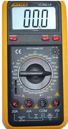
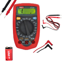 In the following example, we will briefly introduce the usage and precautions of this type of digital multimeter.
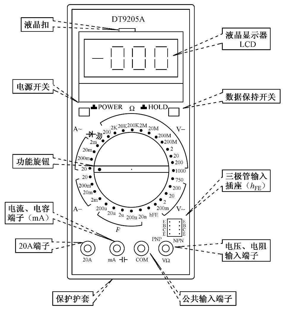

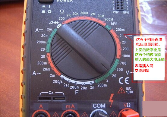
1. Insert the black probe into the com port and the red probe into the VΩ port.
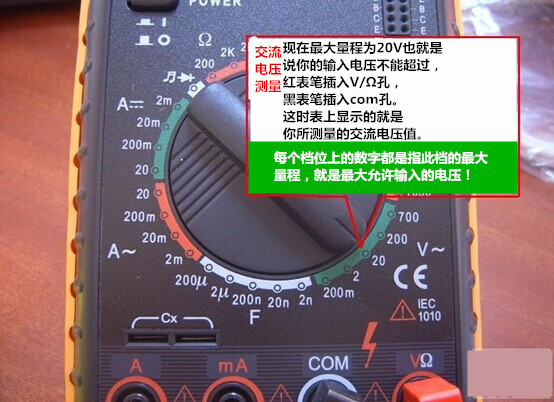
2. Turn the function switch to V~ (AC), V- (DC), and select the appropriate range.
3. Touch the red probe to the positive terminal of the circuit being tested, and the black probe to the ground or negative terminal, i.e., in parallel with the circuit being tested.
4. Read the number displayed on the LCD screen.
1. Turn off the power to the circuit.
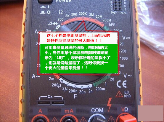
2. Select the resistance range (Ω).
3. Insert the black test probe into the COM input jack. Insert the red test probe into the Ω input jack.
4. Connect the probe tips across the two ends of the device or the part of the circuit you want to measure.
5. Check the reading, confirming the measurement unit—ohms (Ω), kilohms (kΩ), or megaohms (MΩ).
① Judging the condition of the diode: Set the dial to (  ) mode, insert the red probe into the rightmost hole, and the black probe into the second right hole. Connect the probe tips to the two terminals of the diode as shown below, then reverse the probes and measure again.
Measurement results: If the results of the two measurements are: one shows “1” and the other shows a low number, then this diode is a normal diode. If both measurements show the same result, then this diode is damaged. The number displayed on the LCD indicates the forward voltage drop of the diode: about 0.6V for silicon material; about 0.2V for germanium material. Based on the characteristics of the diode, it can be inferred that the red probe is connected to the positive terminal of the diode and the black probe to the negative terminal.
The most important characteristic of a diode is:
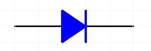
Unidirectional Conductivity
② Short Circuit Test (Judging Circuit Continuity):
Set the dial to short circuit (  ) mode, probe positions are the same as above. Use the other ends of the probes to connect to the two points being tested. If these two points are indeed shorted, the multimeter’s buzzer will sound.
1. Disconnect the circuit;
2. Insert the black probe into the com port, and the red probe into the mA or 20A port;
3. Turn the function switch to A~ (AC), A- (DC), and select the appropriate range;
4. Disconnect the circuit being tested, and connect the digital multimeter in series into the circuit being tested. The current in the circuit flows into the red probe from one end, exits through the black probe, and then flows back into the circuit;
5. Reconnect the circuit;
6. Read the number displayed on the LCD screen.
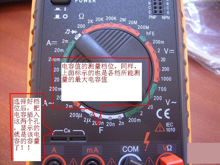
1. Short the capacitor terminals to discharge it, ensuring the safety of the digital multimeter.
2. Set the function switch to the capacitance (C) measurement range and select the appropriate range.
3. Insert the capacitor into the C-X socket of the multimeter.
4. Read the number displayed on the LCD screen.
Quick Tip: Units of capacitance:
1F=1000mF=1000uF=1000nF=1000pF
1. If you cannot estimate the voltage or current to be measured in advance, you should first set it to the highest range and measure once, then gradually reduce the range to an appropriate position. After measurement, set the range switch to the highest voltage range and turn off the power.
2. When at full scale, the instrument will only display the number “1” at the highest position, and all other positions will disappear. At this time, you should select a higher range.
3. When measuring voltage, the digital multimeter should be connected in parallel with the circuit being tested. When measuring current, it should be connected in series with the circuit being tested, and when measuring DC, there is no need to consider polarity.
4. When mistakenly using the AC voltage range to measure DC voltage, or mistakenly using the DC voltage range to measure AC voltage, the display will show “000”, or the numbers at the low position will fluctuate.
5. Do not change the range while measuring high voltage (above 220V) or large current (above 0.5A) to prevent arcing and burning the switch contacts.
Good materials—need to share!
Click to read the original text to learn about PLC, mechanical drawing, CNC robot knowledge