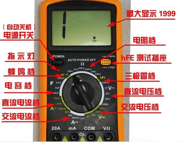
A digital multimeter, a versatile electronic measuring instrument, typically includes functions such as an ammeter, voltmeter, and ohmmeter. It is sometimes referred to as a multitester, multi-tester, multimeter, or three-in-one meter.
1. Buzzer Test
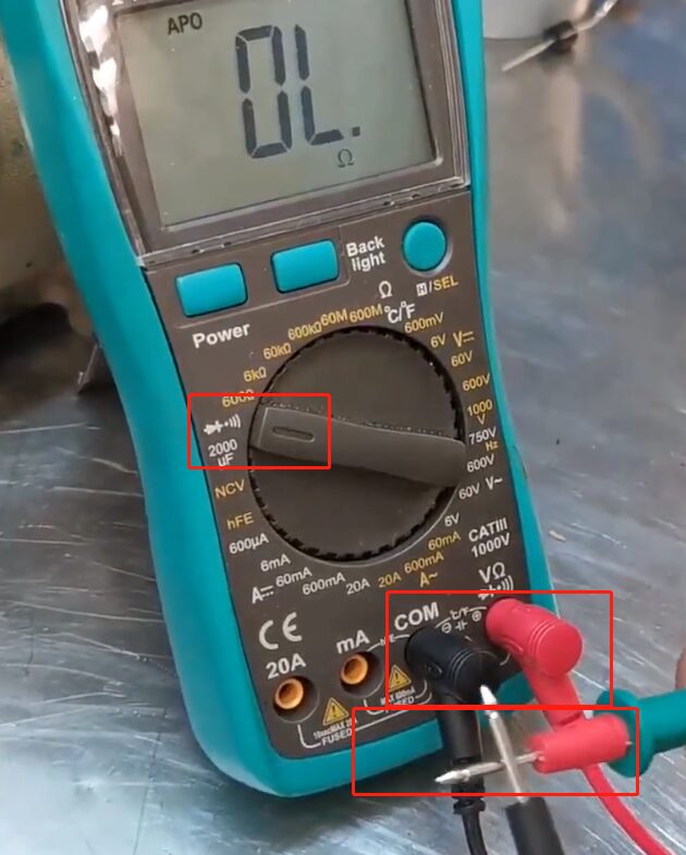
Before using the multimeter, perform a buzzer test to ensure the multimeter is functioning properly. Connect the red probe to the voltage/resistance socket and the black probe to the ground/COM socket. Turn the knob to the buzzer setting as shown in the figure, and turn on the buzzer switch. Connect the red and black probes together; if you hear a “beep” sound, the multimeter is normal. Additionally, the buzzer function can be used to check the continuity of wire harnesses.
2. Voltage Measurement
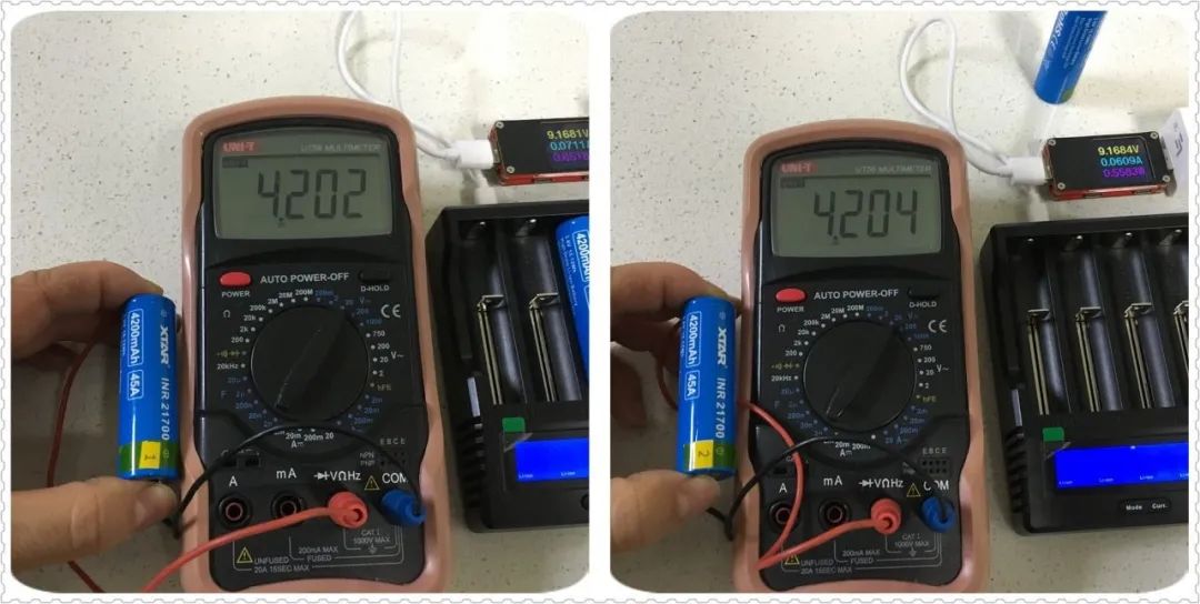
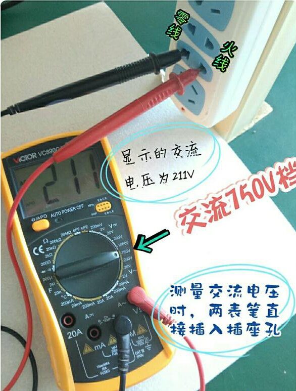
1. Measuring DC voltage, such as battery or portable audio player power supply. First, insert the black probe into the “com” hole and the red probe into the “V Ω” hole. Set the knob to a range larger than the estimated value (Note: The values on the dial represent the maximum range, “V-” indicates the DC voltage range, “V~” indicates the AC voltage range, and “A” is the current range). Connect the probes to both ends of the power supply or battery; maintain stable contact. The value can be read directly from the display. If it shows “1,” it indicates the range is too small, so increase the range and measure the industrial appliance again. If a “-” appears on the left side of the value, it indicates that the probe polarity is opposite to the actual power polarity, meaning the red probe is connected to the negative terminal.
3. Current Measurement
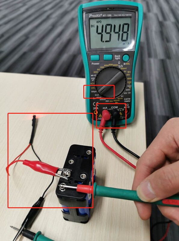
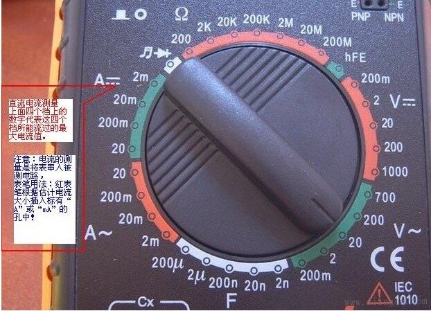
1. Measuring DC current. First, insert the black probe into the “COM” hole. If measuring a current greater than 200mA, insert the red probe into the “10A” socket and turn the knob to the DC “10A” setting; if measuring a current less than 200mA, insert the red probe into the “200mA” socket and set the knob to an appropriate range within 200mA. Once adjusted, the multimeter can be connected in series with the circuit to take readings. If it shows “1,” increase the range; if a “-” appears on the left side of the value, it indicates that the current is flowing into the multimeter from the black probe. If the probes are reversed during measurement, it will display a result such as “-150mA”.
2. Measuring AC current. The measurement method is the same as in step 1, but the setting should be switched to the AC range. After measuring the current, the red probe should be returned to the “VΩ” socket; forgetting this step and measuring voltage directly could damage the multimeter or the power supply.
4. Resistance Measurement
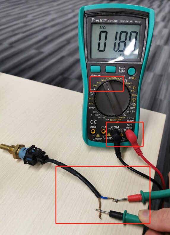
Insert the probes into the “COM” and “VΩ” sockets, and turn the knob to the desired resistance range. Connect the probes to the metal parts of the resistor. While measuring, you can touch the resistor with your hands, but do not touch both ends of the resistor at the same time, as this will affect measurement accuracy—the human body is a conductor with high but limited resistance. When reading, ensure good contact between the probes and the resistor; note the units: in the “200” range, the unit is “Ω”; in the “2K” to “200K” range, the unit is “KΩ”; and above “2M,” the unit is “MΩ.” Wait for the value on the multimeter to stabilize before reading the resistance value.
5. Capacitance Measurement
Some digital multimeters have a capacitance measurement function, with ranges of 2000p, 20n, 200n, 2μ, and 20μ. To measure, set the range switch to the corresponding CAP range, adjust the zero setting knob to make the initial value 0, then insert the capacitor directly into the capacitor testing socket. The display will show the capacitance value. Do not touch the capacitor’s electrode leads or the metal ends of the probes with your hands during measurement, as this may cause the digital multimeter to jump readings or even overload.
6. Diode Measurement
The digital multimeter can measure light-emitting diodes and rectifier diodes. The probe positions are the same as for voltage measurement; set the knob to the diode setting. Connect the red probe to the positive terminal of the diode and the black probe to the negative terminal. The display will show the forward voltage drop of the diode. The forward voltage drop for a Schottky diode is around 0.2V, for standard silicon rectifier diodes (1N4000, 1N5400 series, etc.) it is about 0.7V, and for light-emitting diodes, it is about 1.8 to 2.3V. If the probes are reversed, the display will show “1,” which is normal, as the reverse resistance of the diode is very high; otherwise, the diode has been damaged.
7. Transistor Measurement
The probe positions are the same as above; the principle is the same as for diodes. Assume that pin A is the base; connect the black probe to this pin and the red probe to the other two pins respectively. If both readings are around 0.7V, then pin A is the base; otherwise, the transistor is a PNP type. How to determine the collector and emitter? A digital multimeter cannot use pointer swing to determine like an analog meter. Instead, we can use the “hFE” setting: set the knob to the “hFE” range, and you will see a row of small sockets for measuring PNP and NPN transistors. (Copyright © https://www.diangon.com/) Having determined the type of transistor, insert the base into the corresponding “b” socket, and the other two pins into the “c” and “e” sockets. The value displayed will be the β value; then switch the other two pins and compare the two readings. The larger reading corresponds to the pin marked “c” or “e” on the surface.
Important Note:
When using a digital multimeter to measure voltage parameters, if you do not know the approximate range of the voltage being measured, first set the measurement range to the highest setting. After measuring the value, switch to a lower range for a more accurate reading. If the voltage you are measuring exceeds the maximum range of the multimeter, you should use a high-resistance measurement probe.