Introduction
To achieve better development speed and future iterations and portability of products, layered frameworks are essential.
However, strictly adhering to these principles for small to medium-sized projects can consume excessive energy in system design, which is a decision-making process.
1. What is Layered Framework?
In embedded architecture, it is generally divided into hardware architecture and software architecture. Here we focus on embedded software design, which is the design most people encounter.
The so-called layering can also be understood as modular design, but the design of layered frameworks generally follows the following principles:
-
The interfaces provided by each module must be unified; they can only be added, not modified. Compatibility must be considered during design, including ease of use.
-
Modules at the same level must be independent of each other, cannot affect each other, and can only call the interfaces of the next lower layer.
-
Different modules constitute different layers, and layers cannot call each other across levels.
-
Modules can further be layered, and layers can be added or removed based on project requirements.
Generally, it can be divided into: hardware driver layer -> functional module layer -> application interface layer -> business logic layer -> application layer.
Let’s take a look at this classic diagram to understand the layered framework.
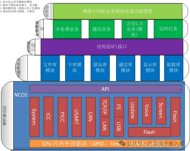
From the diagram, it is not difficult to observe that the design follows the principles of design, and layers cannot call each other.
2. Advantages and Disadvantages of Layered Framework
1. Advantages
-
Single Responsibility: Each layer is responsible for a single responsibility, with clear boundaries, preventing cross-level calls. In large projects, different people are responsible for different parts, speeding up the overall project development.
-
High Cohesion: Layering places similar responsibilities in the same layer, with all business logic concentrated in the domain layer. During testing, only the relevant layer needs to be tested, generally without considering issues from other layers.
-
Low Coupling: The dependency relationships are very simple; upper layers can only depend on lower layers, with no circular dependencies.
-
Easy Maintenance: Changes can be easily made. After a platform change, if only the driver is modified, other layers do not need to be changed; only the driver layer needs to be updated, and the functionality of other layers remains unchanged.
-
Easy Reusability: If a functional module changes, only the corresponding functional module needs to be upgraded, and other modules remain unaffected, including the application layer.
To better utilize these advantages, strict adherence to design principles is necessary.
2. Disadvantages
-
High Development Cost: Because multiple layers each bear their own responsibilities, adding functionality requires code changes across multiple layers, inevitably increasing development costs. However, reasonable abstraction and setting appropriate levels based on project needs can reduce development costs.
-
Performance Slightly Lower: Business flows need to be processed through multiple layers of code, which can consume performance.
-
Low Scalability: Due to the coupling between upper and lower layers, some functional changes may involve modifications across multiple layers.
There are both advantages and disadvantages, and decisions need to be made based on project needs. For small to medium-sized projects, layering may not be necessary (if future iterations are not considered), or partial layering may suffice, allowing for some advantages of layered frameworks while reducing development costs.
3. A Simple Example
Since the main discussion is on the layered design of software frameworks, we will use STM32CubeMX for hardware initialization, minimizing consideration of hardware drivers.
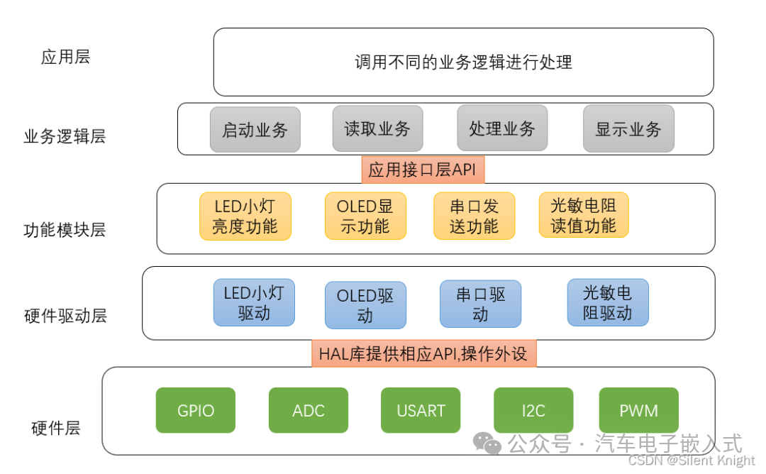
Let’s take a smart light as an example:
Functionality
-
Button controls the brightness of the light, with levels: 0, 1, 2, 3.
-
Serial port can observe the current brightness level of the light.
-
OLED can also observe the current brightness level of the light.
Below is a simple illustration of this example.
This example is relatively simple; the business logic layer can be completely removed, directly calling the functional module layer from the application layer to speed up development.
Finally, here’s a bit of code regarding how to encapsulate the LED across different layers.
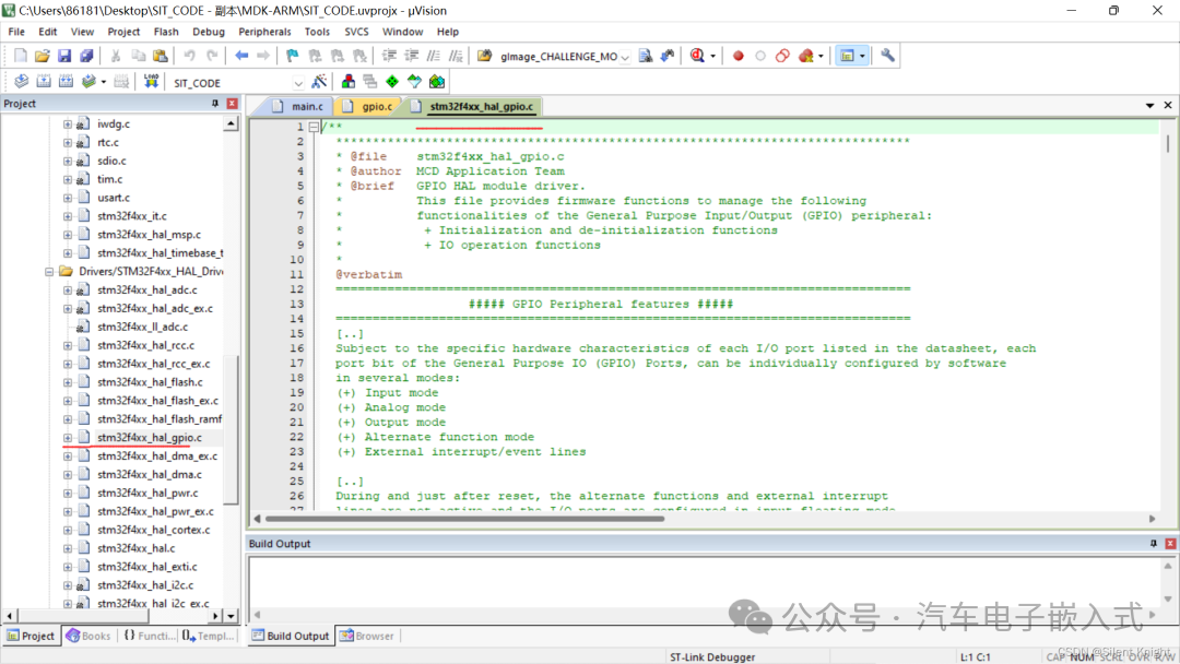
Hardware Layer
First, let’s look at the code provided by the HAL library, which is the LED hardware layer, specifically the GPIO layer. CubeMX has already generated it in stm32f4xx_hal_gpio.c (I am using F4), and there are corresponding GPIO drivers, so we do not need to handle this.
Hardware Driver Layer
Let’s look at the driver for the LED part, which consists of the following two functions:
void MX_TIM1_Init(void);
void HAL_TIM_MspPostInit(TIM_HandleTypeDef* timHandle);
/* TIM1 init function */
void MX_TIM1_Init(void)
{

/* USER CODE BEGIN TIM1_Init 0 */

/* USER CODE END TIM1_Init 0 */

  TIM_ClockConfigTypeDef sClockSourceConfig = {0};
  TIM_MasterConfigTypeDef sMasterConfig = {0};
  TIM_OC_InitTypeDef sConfigOC = {0};
  TIM_BreakDeadTimeConfigTypeDef sBreakDeadTimeConfig = {0};

/* USER CODE BEGIN TIM1_Init 1 */

/* USER CODE END TIM1_Init 1 */
  htim1.Instance = TIM1;
  htim1.Init.Prescaler = 168-1;
  htim1.Init.CounterMode = TIM_COUNTERMODE_UP;
  htim1.Init.Period = 10000;
  htim1.Init.ClockDivision = TIM_CLOCKDIVISION_DIV1;
  htim1.Init.RepetitionCounter = 0;
  htim1.Init.AutoReloadPreload = TIM_AUTORELOAD_PRELOAD_ENABLE;
if (HAL_TIM_Base_Init(&htim1) != HAL_OK)
  {
    Error_Handler();
  }
  sClockSourceConfig.ClockSource = TIM_CLOCKSOURCE_INTERNAL;
if (HAL_TIM_ConfigClockSource(&htim1, &sClockSourceConfig) != HAL_OK)
  {
    Error_Handler();
  }
if (HAL_TIM_PWM_Init(&htim1) != HAL_OK)
  {
    Error_Handler();
  }
  sMasterConfig.MasterOutputTrigger = TIM_TRGO_RESET;
  sMasterConfig.MasterSlaveMode = TIM_MASTERSLAVEMODE_DISABLE;
if (HAL_TIMEx_MasterConfigSynchronization(&htim1, &sMasterConfig) != HAL_OK)
  {
    Error_Handler();
  }
  sConfigOC.OCMode = TIM_OCMODE_PWM1;
  sConfigOC.Pulse = 0;
  sConfigOC.OCPolarity = TIM_OCPOLARITY_HIGH;
  sConfigOC.OCNPolarity = TIM_OCNPOLARITY_HIGH;
  sConfigOC.OCFastMode = TIM_OCFAST_DISABLE;
  sConfigOC.OCIdleState = TIM_OCIDLESTATE_RESET;
  sConfigOC.OCNIdleState = TIM_OCNIDLESTATE_RESET;
if (HAL_TIM_PWM_ConfigChannel(&htim1, &sConfigOC, TIM_CHANNEL_2) != HAL_OK)
  {
    Error_Handler();
  }
  sBreakDeadTimeConfig.OffStateRunMode = TIM_OSSR_DISABLE;
  sBreakDeadTimeConfig.OffStateIDLEMode = TIM_OSSI_DISABLE;
  sBreakDeadTimeConfig.LockLevel = TIM_LOCKLEVEL_OFF;
  sBreakDeadTimeConfig.DeadTime = 0;
  sBreakDeadTimeConfig.BreakState = TIM_BREAK_DISABLE;
  sBreakDeadTimeConfig.BreakPolarity = TIM_BREAKPOLARITY_HIGH;
  sBreakDeadTimeConfig.AutomaticOutput = TIM_AUTOMATICOUTPUT_DISABLE;
if (HAL_TIMEx_ConfigBreakDeadTime(&htim1, &sBreakDeadTimeConfig) != HAL_OK)
  {
    Error_Handler();
  }
/* USER CODE BEGIN TIM1_Init 2 */

/* USER CODE END TIM1_Init 2 */
  HAL_TIM_MspPostInit(&htim1);
}

void HAL_TIM_MspPostInit(TIM_HandleTypeDef* timHandle)
{

  GPIO_InitTypeDef GPIO_InitStruct = {0};
if(timHandle->Instance==TIM1)
  {
/* USER CODE BEGIN TIM1_MspPostInit 0 */

/* USER CODE END TIM1_MspPostInit 0 */

    __HAL_RCC_GPIOE_CLK_ENABLE();
    /**TIM1 GPIO Configuration
    PE11     ------> TIM1_CH2
    */
    GPIO_InitStruct.Pin = GPIO_PIN_11;
    GPIO_InitStruct.Mode = GPIO_MODE_AF_PP;
    GPIO_InitStruct.Pull = GPIO_NOPULL;
    GPIO_InitStruct.Speed = GPIO_SPEED_FREQ_LOW;
    GPIO_InitStruct.Alternate = GPIO_AF1_TIM1;
    HAL_GPIO_Init(GPIOE, &GPIO_InitStruct);

/* USER CODE BEGIN TIM1_MspPostInit 1 */

/* USER CODE END TIM1_MspPostInit 1 */
  }
}
Encapsulating it gives us the desired LED light driver; if needed, we can directly modify the driver at the bottom layer.
void Led_init()
{
 MX_TIM1_Init();
 HAL_TIM_PWM_Start(&htim1,TIM_CHANNEL_2);// Start PWM
}
Functional Module Layer
Based on the above requirements, it is divided into four different levels, and the LED driver also needs further encapsulation to meet the principle that layers cannot call each other across levels (isn’t it cumbersome at this point? For small projects, it’s better not to use it!).
// ARR counter setting value from 0 to 10000
#define LED_GRADE_0  0
#define LED_GRADE_1  3000
#define LED_GRADE_2  6000
#define LED_GRADE_3  10000
// Set LED brightness function
void Led_Set_brightness(int Grade)
{
if(Grade==LED_GRADE_0)
 {
     __HAL_TIM_SET_COMPARE(&htim1, TIM_CHANNEL_2, Grade);
  HAL_TIM_PWM_Stop(&htim1,TIM_CHANNEL_2);// Stop PWM output
 }
else
 {
  HAL_TIM_PWM_Start(&htim1, TIM_CHANNEL_2, Grade);
  __HAL_TIM_SET_COMPARE(&htim1, TIM_CHANNEL_2, Grade);
 }
}

// Start LED function
void Led_Start()
{
 Led_init();
}
Business Logic Layer
Here, we take the start layer as an example:
void Start_app()
{
 Led_Start();
}
Application Layer
The basic flow is: start business logic -> read business logic -> process business logic -> display business logic.
4. Conclusion
At this point, a simple example has been explained. Through this simple example of LED, we have roughly understood the complexity of this design.
For large projects, it will be very enjoyable to use; for small ones, it is completely unnecessary to layer this way, as it is too cumbersome and severely slows down development efficiency, with time spent thinking about how to layer to conform to the principles of layered frameworks.
Original Article:https://blog.csdn.net/weixin_46185705/article/details/122536374
The source of this article is from the internet, and the copyright belongs to the original author. If there is any infringement, please contact for deletion.