Introduction
In the field of industrial automation, stepper motors are widely used in various applications requiring precise positioning, such as automated production lines, CNC machine tools, and robotics, due to their accurate position control capabilities and simple control methods. This article provides a detailed design scheme for a complete stepper motor control system based on the Mitsubishi FX series PLC, including system requirement analysis, hardware selection, circuit design, program writing, and debugging techniques. Through this technical guide, engineers and technicians can quickly master the PLC control methods for stepper motors, enhancing the efficiency of automation equipment development.

1. System Requirement Analysis
1.1 Project Overview
This project requires the design of a stepper motor control system based on Mitsubishi PLC to achieve precise positioning control of the workbench. The system consists of a touch screen, PLC, stepper motor, and driver, capable of manual control and automatic cycle control functions.
1.2 Control Requirements
The system must meet the following control requirements:
- Manual Mode allows for forward and reverse control of the motor.
- Home Return Pressing the home return button will automatically return the system to the home position; only after returning to the home position can it enter automatic mode.
- Automatic Mode After completing the home return, pressing the start button will cause the motor to run in a loop to the set positions (Position 1 → Position 2 → Position 3 → Position 4 → Position 5 → Position 1).
- Emergency Stop Function Pressing the emergency stop button will immediately stop the motor, requiring a return to the home position to be executed again.
- Pause Function Pressing the pause button will stop the device; pressing the start button again will resume operation.
1.3 Technical Parameters
- Stepper Motor Step Angle: 1.8°
- Pitch: 2mm
- Subdivision Setting: 4
- Limit Switches: X5 (negative limit), X4 (home), X3 (positive limit)
2. Hardware System Design
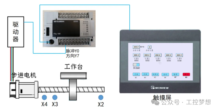
2.1 Electrical Component Selection
| Component Name | Model Specification | Quantity | Purpose |
|---|---|---|---|
| PLC | Mitsubishi FX Series | 1 unit | Main controller |
| Stepper Motor | 42BYCH47-401A | 1 unit | Actuator |
| Stepper Motor Driver | Compatible model | 1 unit | Motor drive |
| Touch Screen | Weinview Series | 1 unit | Human-machine interaction |
| Limit Switch | Photoelectric Sensor | 3 units | Position detection |
| Buttons | Emergency stop, start, pause, etc. | Several | Operational control |
2.2 I/O Allocation
Input Signals:
| Input Point | Label | Function Description |
|---|---|---|
| X3 | Positive Limit | Positive direction limit protection |
| X4 | Home | Home position detection |
| X5 | Negative Limit | Negative direction limit protection |
| M2 | Manual/Automatic | Manual/Automatic mode switching |
| M3 | Forward | Manual forward control |
| M4 | Reverse | Manual reverse control |
| M5 | Home Return | Home return control |
| M6 | Start | Automatic run start |
| M7 | Pause | Run pause control |
| M8 | Stop | Emergency stop control |
Output Signals:
| Output Point | Label | Function Description |
|---|---|---|
| Y0 | Pulse Output | Stepper motor pulse signal |
| Y7 | Direction Output | Stepper motor direction signal |
2.3 Motor Wiring Scheme
The wiring diagram of the stepper motor and PLC is as follows:
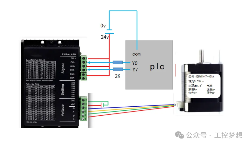
- PLC Output Y0 (Pulse) → Driver PUL+
- PLC Output Y7 (Direction) → Driver DIR+
- Driver PUL-, DIR- → PLC COM terminal
- Driver ENA+, ENA- → 24V power supply
- Motor coils A+, A-, B+, B- → Driver corresponding terminals
Notes:
- Ensure the power supply voltage matches the driver (usually 20-50VDC)
- Correctly connect the motor coils to avoid reverse rotation
- Use shielded cables to reduce electromagnetic interference
3. Control Program Design
3.1 Manual Control Program
In manual mode, the motor’s forward and reverse control is managed through touch screen buttons:
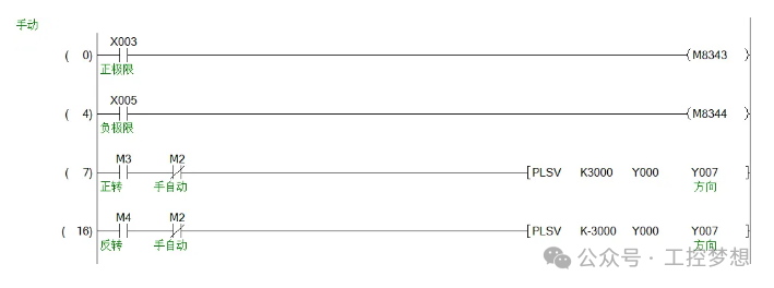
3.2 Home Return Program
The home return is a prerequisite for automatic operation, with the following implementation steps:
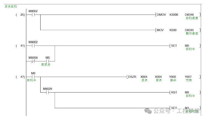
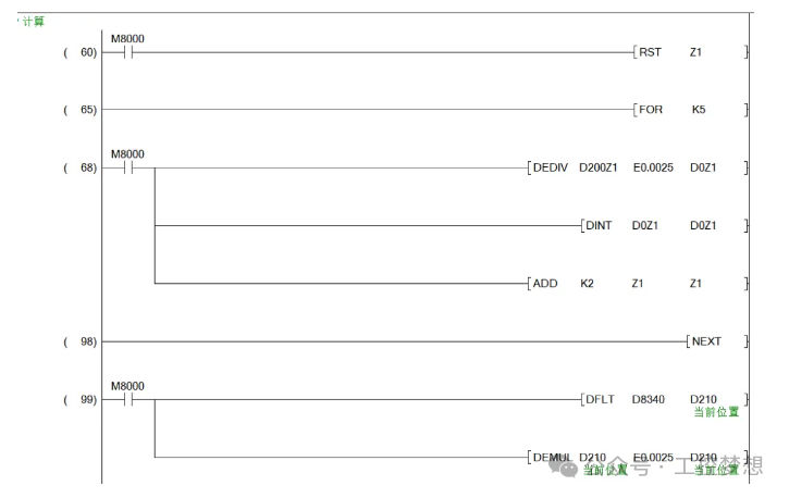
3.3 Position Data Calculation
Based on the stepper motor parameters, calculate the pulse count for each position:
- Step angle: 1.8°, subdivision 4 → Angle per pulse: 0.45°
- Pulses per revolution: 360° ÷ 0.45° = 800 pulses/revolution
- Pulse equivalent: 2mm ÷ 800 = 0.0025mm/pulse
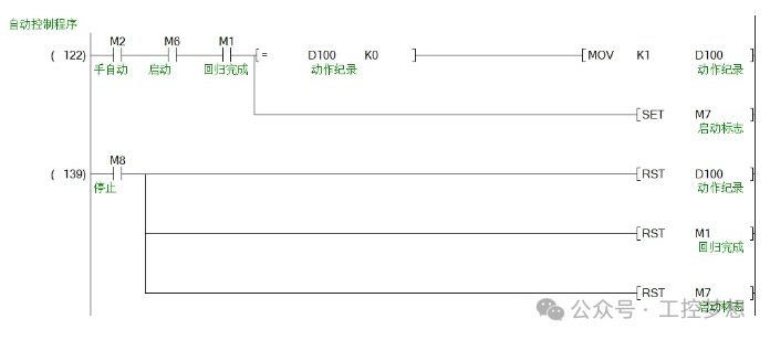
3.4 Automatic Control Program
In automatic mode, implement position loop control:
 Sequential control implementation: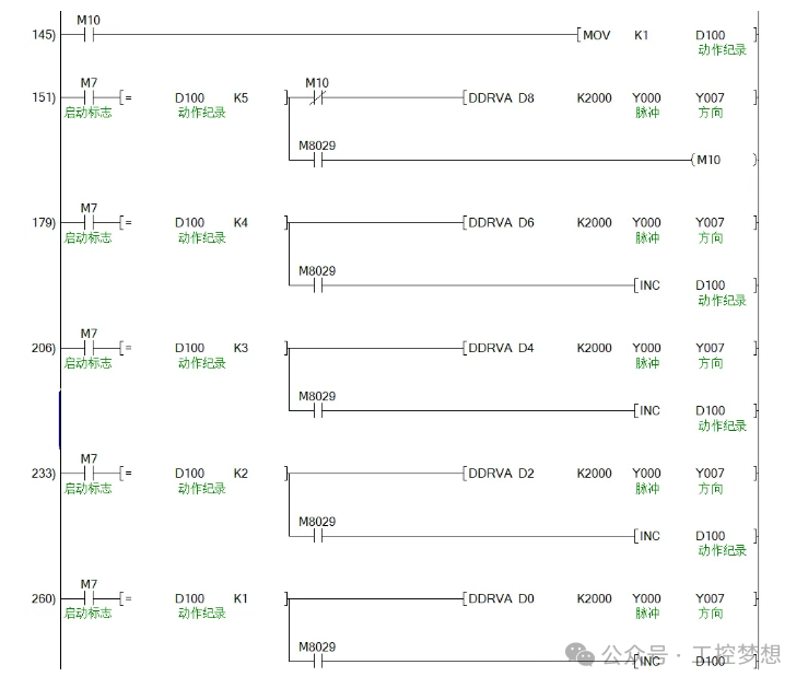
4. System Debugging and Optimization
4.1 Debugging Steps
-
Hardware Debugging:
- Check if the power supply wiring is correct
- Confirm that all sensor wiring is correct
- Test if all button functions are normal
Software Debugging:
- Manual mode test: Verify forward and reverse functions
- Home return test: Check if the return action is normal
- Automatic mode test: Verify position loop control
- Emergency stop and pause test: Test exception handling functions
4.2 Common Problem Solutions
| Problem Phenomenon | Possible Cause | Solution |
|---|---|---|
| Motor does not rotate | Power failure or wiring error | Check power supply and wiring |
| Motor loses steps | Speed too fast or load too heavy | Reduce speed or optimize mechanical structure |
| Home return failure | Home sensor failure | Check sensor and wiring |
| Automatic operation abnormal | Program logic error | Check sequential control logic |
4.3 System Optimization Suggestions
- Acceleration and Deceleration Control Add S-curve acceleration and deceleration to avoid mechanical shock
- Fault Diagnosis Add fault alarm and diagnosis functions
- Parameter Optimization Adjust operating speed and acceleration based on actual load
- Data Logging Add operational data logging function for maintenance convenience
5. Conclusion
This article provides a detailed introduction to the design and implementation methods of a stepper motor control system based on Mitsubishi PLC, offering a complete solution from system requirement analysis, hardware selection, software programming to system debugging. The system features manual/automatic control, home return, sequential control, emergency stop protection, and can be widely applied in various automation devices requiring precise positioning.
In practical applications, parameters and program logic should be adjusted according to specific working conditions to ensure stable and reliable system operation. The key to designing a stepper motor control system lies in reasonable hardware configuration, precise parameter calculation, and comprehensive protection mechanisms, all of which are indispensable.
It is hoped that this article can provide valuable references for engineers and technicians in the field of industrial automation, assisting everyone in quickly achieving efficient and reliable stepper motor control systems in practical projects.
Previous Recommendations
Can’t connect to S7 communication? The “ping + diagnostic buffer” troubleshooting method that 90% of engineers don’t know (with flowchart)
Double your efficiency! 30 shortcuts secretly kept by EPLAN experts, a must-have for electrical engineers
Three highly efficient solutions for PLC data acquisition! From local to cloud, a 10-year engineer’s practical summary!
Reflections on “The Little Monsters of Langlang Mountain”: Unsung heroes in ordinary positions!
Learn analog control from 0 to 1, just one temperature control case is enough!
Seven major pitfalls in PLC programming summarized by a 10-year engineer! Each error comes with a solution!
The most intuitive and comprehensive CAD shortcuts: 90 core commands to boost drawing efficiency by 100%
Recruitment for students! Direct phone calls for those with composite conditions ☎
No serial port on S7-1200? 3 steps to expand RS485 communication, an official module pit avoidance guide!
Monthly salary from 3,000 to 30,000! A comprehensive guide for electrical engineers to reverse their careers in 3 years: 5 secrets from wiring workers to technical directors!
Quick start for beginners – Mitsubishi single-button start-stop control of equipment operation!
Send me your resume! A listed company in Changsha is recruiting after-sales electrical engineers!
Complete guide to S7-1200 FC block encryption and decryption: 3 pitfalls that 90% of engineers have encountered
Absolute encoder detailed explanation: principles, selection, and industrial application guide!
Must-know issues for learning Siemens S7-1200 PLC programming: A practical guide from basics to advanced!
Beginner’s guide to electricians: The transformation journey from “electric blind” to “electrician”!
Three major fatal errors in PLC programming! 90% of engineers have fallen into these traps!
Zhang Xuefeng is right! Automation PLC is indeed attractive! – Revealing the four core advantages of the industry in the next decade
From principles to practice: A development guide for valve control programs with feedback mechanisms!
Several control modes of servo motors, if you don’t know, you’re OUT!
About Us – Jicheng Introduction!