Word count: 8843, reading time approximately 45 minutes
A Comprehensive Comparison of UART and SPI in Embedded Systems
UART and SPI are key communication methods in the electronics field. UART is suitable for simple long-distance connections, while SPI excels in fast data transmission. They are used in GPS modules, SD cards, and microcontrollers, and understanding their differences can help you choose the best option for any given project.
Introduction
UART (Universal Asynchronous Receiver-Transmitter) and SPI (Serial Peripheral Interface) are protocols used for communication between electronic devices. They play a crucial role in enabling a “smooth dialogue” between components of electronic devices.
UART is known for its simplicity and reliability over long distances, making it very suitable for tasks such as connecting a GPS module to a computer. On the other hand, SPI is built for speed, making it ideal for fast data transfers, such as reading data from an SD card or controlling a microcontroller. This article will delve into the operation and unique advantages of each protocol, showing you how understanding these differences can help you choose the right protocol for your project. Curious about which protocol might save you time or enhance your device’s performance? Read on to find out!
The Basics of Serial Communication
Serial communication forms the foundation of data exchange in embedded systems, allowing efficient transmission of information between microcontrollers, sensors, and peripherals. At its core, serial communication involves transmitting data bits sequentially over a single communication channel. This method contrasts with parallel communication, where multiple bits are sent simultaneously over multiple channels.
In embedded systems, serial communication offers several advantages, such as reduced pin count, simplified wiring, and improved noise immunity. These advantages make serial communication particularly suitable for resource-constrained environments and long-distance data transmission.
Serial data transmission typically includes start and stop bits to mark individual data frames, ensuring proper synchronization between electronic devices.
Serial protocols can be broadly classified into two categories: synchronous and asynchronous. Synchronous communication relies on a shared clock signal to coordinate data transmission, ensuring precise timing between the transmitter and receiver. Examples include SPI (Serial Peripheral Interface) and I2C (Inter-Integrated Circuit). In contrast, asynchronous communication, exemplified by UART (Universal Asynchronous Receiver-Transmitter), does not require a shared clock but instead uses start and stop bits to mark data and maintains synchronization using a predefined baud rate.
To illustrate serial data transmission, consider the following diagram:
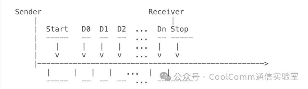
This diagram depicts a typical serial data frame, where each bit (D0 to Dn) is transmitted sequentially, packed between the start and stop bits. The unidirectional arrows indicate the flow of data from the transmitter to the receiver over time.
UART: Universal Asynchronous Receiver-Transmitter
Architecture and Operation
UART (Universal Asynchronous Receiver-Transmitter) is a hardware component that plays a crucial role in serial port communication between devices. At a high level, the UART interface is responsible for converting parallel data (processing multiple bits simultaneously) into a serial stream (sending one bit at a time) and vice versa. It reverts incoming serial data back into parallel form. This makes UART essential for data exchange between microcontrollers, sensors, and other peripherals.
UART consists of two main parts: the transmitter and the receiver. The transmitter takes parallel data from the device, converts it one bit at a time, and transforms it into a serial stream. The receiver, on the other hand, collects incoming serial data bit by bit and converts it back into parallel data that the device can use. These processes occur independently, allowing for simultaneous sending and receiving of data, i.e., full-duplex (bidirectional) communication.
A key feature of UART is its asynchronous nature, meaning that communication devices do not need to share a clock signal. Instead, both the transmitter and receiver agree on a specific baud rate, which is the speed of data transmission measured in bits per second (bps). As long as both devices are set to the same baud rate, they can maintain proper synchronization and communicate effectively. This simplicity and flexibility make UART a widely used protocol in embedded systems and other electronic devices.
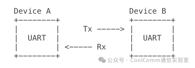
A typical UART setup involves connecting one device’s Tx (transmit) pin to another device’s Rx (receive) pin, and vice versa, as shown in the circuit diagram below:
UART data transmission follows a specific timing sequence. Each data frame begins with a start bit (logic low), followed by data bits (typically 5 to 9 bits), an optional parity bit for error checking, and one or more stop bits (logic high). The timing diagram below illustrates this sequence:
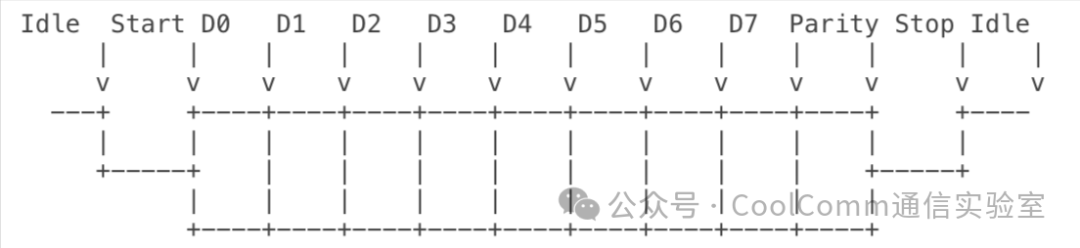
This asynchronous frame structure allows devices to maintain synchronization without a shared clock, making UART a common and flexible protocol in embedded systems. The flexibility in baud rate selection and frame configuration allows UART to adapt to various communication needs in different applications.
Data Frames in UART
UART communication relies on a well-defined frame structure to ensure reliable data transmission. A typical UART frame consists of several parts: start bit, data bits, optional parity bit, and stop bits. This structure allows the receiver to synchronize with the incoming data and interpret it correctly.
The frame begins with a start bit, always set to logic low (0), indicating the start of a new data transmission. Following the start bit are the data bits, which carry the actual information. UART supports flexible data lengths, typically ranging from 5 to 9 bits, with 8 bits being the most common in modern systems.
After the data bits, an optional parity bit can be enabled for basic error detection in noisy environments, or disabled in more reliable connections to reduce overhead. The parity bit can be configured for even parity, odd parity, or completely omitted. Even parity ensures that the total number of 1 bits in the data bits plus the parity bit is even, while odd parity aims for an odd total.
The frame ends with one or more stop bits, set to logic high (1). These bits mark the end of the frame and provide a brief pause before the next frame begins. Typically, 1, 1.5, or 2 stop bits are used.
Below is a visual representation of a UART data frame:
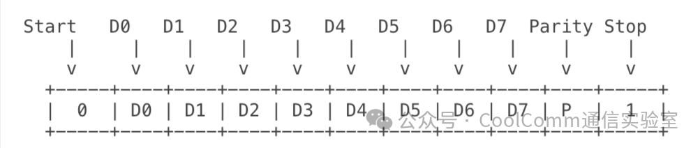
The flexibility of UART frame configuration allows engineers to adjust the protocol according to various application needs. For example, shorter data lengths can be used for simple control signals, while longer lengths are suitable for more complex data transmissions.
To configure UART frames in software, developers typically interact with UART control registers. Below is a pseudocode example demonstrating how to configure a UART frame:
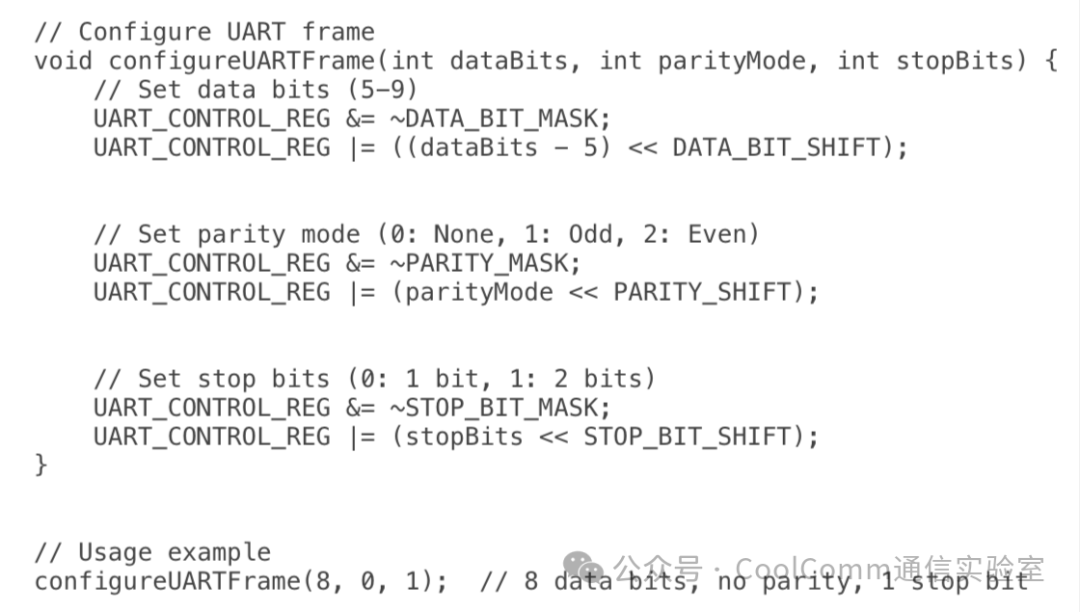
This configurability allows UART to adapt to various communication needs, making it a universal choice in many embedded system applications.
SPI: Serial Peripheral Interface
Architecture and Operation
The Serial Peripheral Interface (SPI) is a synchronous serial port communication protocol widely used for high-speed, short-distance communication between microcontrollers and peripheral devices in embedded systems. The architecture of SPI is built around four main signal lines:
- 1. MOSI (Master Out Slave In),
- 2. MISO (Master In Slave Out),
- 3. SCLK (Serial Clock), and
- 4. SS (Slave Select, also known as CS or Chip Select).
MOSI and MISO are unidirectional data lines. MOSI transmits data from the master device to the slave device, while MISO transmits data from the slave device to the master device. SCLK (or SCL) is the clock signal generated by the master device to synchronize data transmission. The SS line (or select line) is used to select and activate a specific slave device for communication.
The synchronous nature of SPI is one of its key features. The master device generates the clock signal (SCLK) to synchronize SPI communication between the master and slave devices. Unlike asynchronous protocols (like UART), SPI does not require start and stop bits or complex timing protocols, allowing for higher data transmission rates.
SPI adopts a master-slave configuration, where one device (usually a microcontroller) acts as the master, controlling the clock signal and initiating all communication. The slave device responds to commands from the master and cannot initiate communication on its own. This hierarchy simplifies protocol implementation and reduces the likelihood of bus contention.
A typical SPI setup, which includes multiple slave devices, can be represented by the following circuit diagram:
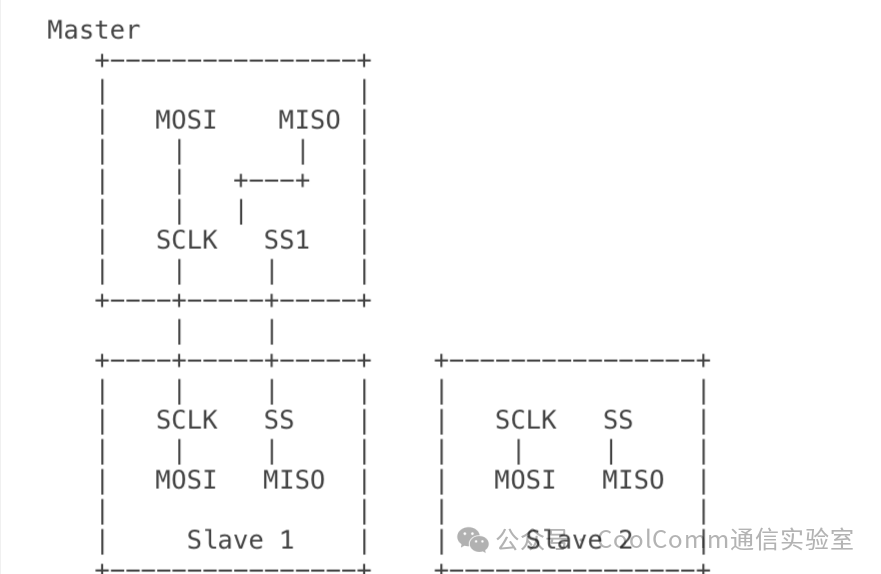
In this setup, the master device can communicate with multiple slave devices by using separate SS lines for each slave device. Only one slave device can be activated at a time, determined by the SS line pulled low by the master device.
The timing diagram below illustrates SPI data transmission:
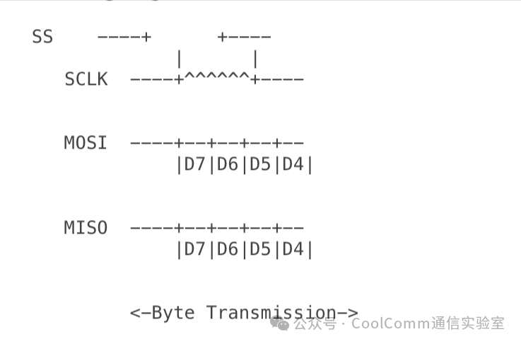
In this diagram, data is typically shifted out on one clock edge (e.g., falling edge) and sampled on another edge (e.g., rising edge). The SPI mode used determines the exact timing.
The architecture and operation of SPI make it very suitable for applications requiring high-speed data transmission between microcontrollers and peripherals (such as sensors, storage devices, and display controllers). Its simplicity and efficiency have led to its widespread adoption in embedded system design.
SPI Modes and Configuration
SPI (Serial Peripheral Interface) supports four different operating modes, each defined by specific clock polarity (CPOL) and clock phase (CPHA) settings. These modes determine how data is synchronized between the master and slave devices.
The four SPI modes are as follows:
- 1. Mode 0 (CPOL = 0, CPHA = 0): Clock idle low, data sampled on the rising edge, shifted out on the falling edge.
- 2. Mode 1 (CPOL = 0, CPHA = 1): Clock idle low, data sampled on the falling edge, shifted out on the rising edge.
- 3. Mode 2 (CPOL = 1, CPHA = 0): Clock idle high, data sampled on the falling edge, shifted out on the rising edge.
- 4. Mode 3 (CPOL = 1, CPHA = 1): Clock idle high, data sampled on the rising edge, shifted out on the falling edge.
The table below summarizes the SPI modes:
| Mode | CPOL | CPHA | Clock Idle State | Data Sampling Edge | Data Shifting Edge |
| 0 | 0 | 0 | Low | Rising Edge | Falling Edge |
| 1 | 0 | 1 | Low | Falling Edge | Rising Edge |
| 2 | 1 | 0 | High | Falling Edge | Rising Edge |
| 3 | 1 | 1 | High | Rising Edge | Falling Edge |
SPI also supports daisy chaining, a configuration where multiple slave devices are connected in series. In this setup, the MISO (Master In Slave Out) of one slave device connects to the MOSI (Master Out Slave In) of the next slave device. This configuration offers several advantages:
- 1. Reduces pin usage on the master device, as multiple slave devices only require one SS (Slave Select) line.
- 2. Simplifies PCB wiring, especially in designs with many SPI devices.
- 3. Allows for the creation of long shift registers for special applications.
However, daisy chaining increases the overall delay in data transmission, as data must pass through all devices in the chain.
To configure SPI modes in software, developers typically interact with SPI control registers. Below is a pseudocode example demonstrating how to configure an SPI mode:
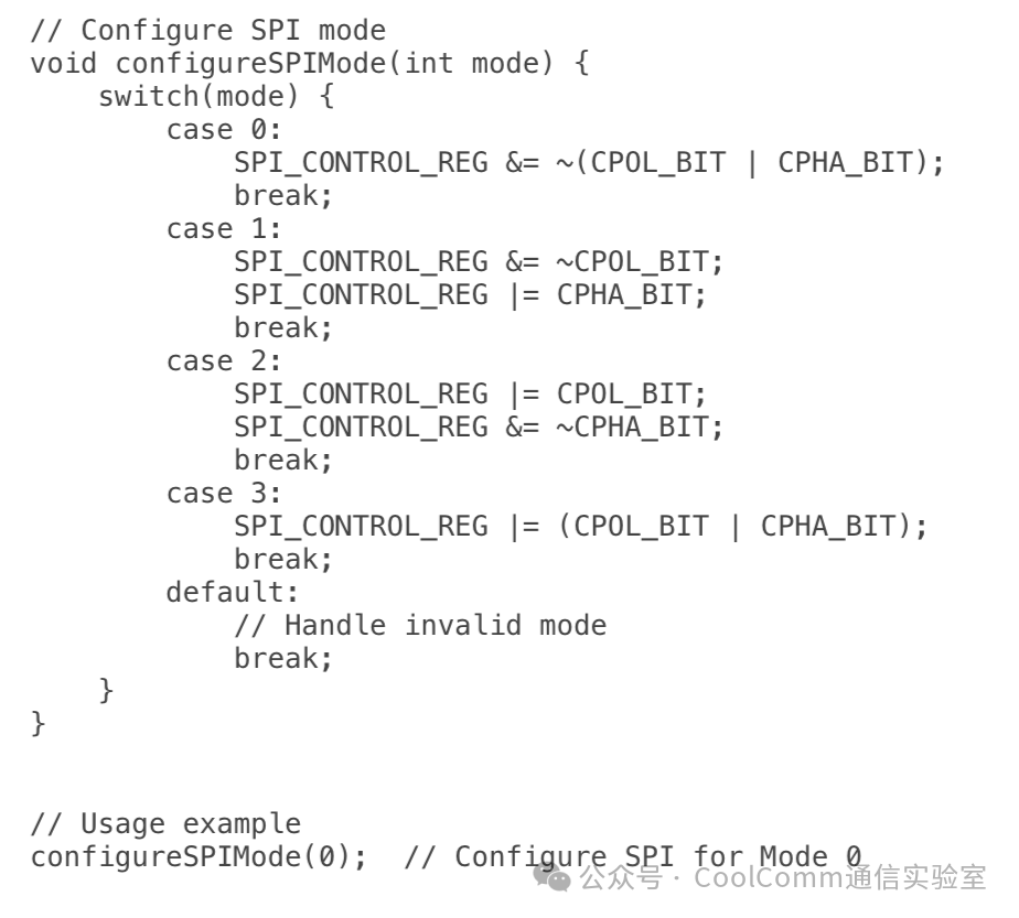
Understanding and correctly configuring SPI modes is crucial for ensuring proper communication between the master and slave devices. The choice of mode depends on the specific requirements of the connected devices and the overall system design.
UART vs. SPI: A Comprehensive Comparison
Speed and Efficiency
When designing embedded systems, the choice between UART and SPI often depends on the required data transmission rate and overall communication efficiency. These factors can significantly impact system performance and power consumption.
UART typically operates at lower speeds compared to SPI. Standard UART baud rates range from 9600 bps to 115200 bps, with some modern implementations reaching 921600 bps. In contrast, SPI can achieve higher data rates, typically ranging from several Mbps to tens of Mbps, with some high-speed implementations reaching 100 Mbps or more.
The overhead in UART communication is greater than that in SPI. A UART frame includes start and stop bits, along with an optional parity bit. For a typical 8-bit data transmission, UART requires at least 10 bits (1 start bit, 8 data bits, 1 stop bit). This overhead results in a 20% reduction in effective data rate. SPI, on the other hand, has minimal overhead, typically only requiring the transmission of the actual data bits.
In terms of data transmission efficiency, the two protocols also differ. The asynchronous nature of UART allows for flexible timing but requires precise baud rate matching between devices. Any mismatch can lead to data corruption. SPI’s synchronous design, with a dedicated clock line, ensures higher data transmission efficiency as the clock signal coordinates data exchange.
The table below compares key speed and efficiency metrics for UART and SPI:
| Metric | UART | SPI |
| Typical Speed Range | 9600 bps – 1 Mbps | 10 Mbps – 50 Mbps |
| Maximum Theoretical Speed | Approximately 10 Mbps | >100 Mbps |
| Overhead per Byte | 2-4 bits (20-33%) | 0 bits (0%) |
| Clock Synchronization | Asynchronous (no clock) | Synchronous (clock line) |
| Efficiency at High Speeds | Reduced due to timing constraints | Maintains high efficiency |
It is important to note that while SPI generally offers higher speed and efficiency, the simplicity and lower pin count of UART may make it the preferred choice in applications where maximum data rate is not critical. When choosing between UART and SPI, it is essential to consider the specific requirements of the embedded system, including the desired data rate, system complexity, and available microcontroller resources.
Hardware Complexity and Pin Usage
In embedded system design, the hardware complexity and pin usage of communication protocols play a critical role in determining the overall system architecture, cost, and power consumption. UART and SPI exhibit significant differences in these aspects, each offering unique advantages and trade-offs.
UART (Universal Asynchronous Receiver-Transmitter) is known for its simplicity in hardware requirements. A basic UART communication link requires only two lines: TX (transmit) and RX (receive). This minimal pin usage makes UART an attractive choice in applications where pin count is a critical constraint. However, when implementing full-duplex communication with hardware flow control, two additional lines (RTS and CTS) may be required, bringing the total to four lines.
In contrast, SPI (Serial Peripheral Interface) requires at least four lines: MOSI (Master Out Slave In), MISO (Master In Slave Out), SCLK (Serial Clock), and SS (Slave Select). This higher pin count allows for more complex communication but increases hardware complexity.
In terms of scalability, UART and SPI exhibit different characteristics. UART is inherently point-to-point, meaning that connecting multiple devices requires additional UART ports on the master device or external multiplexers. This limitation can lead to increased system complexity and cost when scaling to multiple devices.
SPI, on the other hand, is designed for easy scalability. Multiple slave devices can be connected to a single master device using a shared bus topology. Each additional slave device typically only requires one extra SS line from the master, while the MOSI, MISO, and SCLK lines are shared among all devices. This daisy chain configuration allows for efficient scaling of the system with minimal additional wiring as the number of connected devices increases.
The impact on PCB design and wiring is significant for both protocols. The simple wiring scheme of UART often results in cleaner PCB layouts and simpler wiring, especially in space-constrained designs. While SPI requires more signal lines, its synchronous characteristics can lead to more predictable signal integrity and potentially simpler PCB designs for high-speed applications.
To illustrate the differences in connecting multiple devices, consider the following diagram:
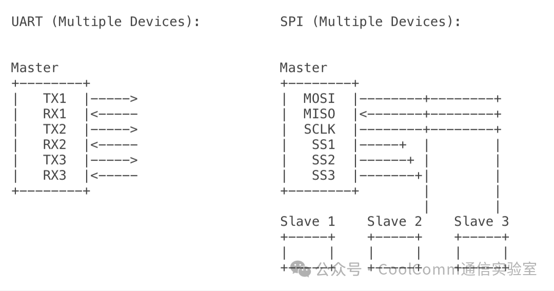
This diagram shows that UART requires a separate TX/RX pair for each device, while SPI can connect multiple slave devices using shared data and clock lines, with each slave device only needing one separate SS line. The SPI configuration may be more scalable and efficiently utilize microcontroller pins as the number of connected devices increases.
UART vs. SPI: Power Consumption
Power consumption is another critical factor to consider when comparing UART and SPI communication protocols, especially in power-sensitive applications such as battery-powered devices and energy harvesting systems.
Due to its asynchronous nature and lack of a continuous clock signal, UART communication typically consumes less power than SPI. The power consumption in a UART system is primarily determined by the baud rate and the number of active communication lines. Reducing the baud rate and minimizing the number of active lines can help minimize power consumption in UART systems.
On the other hand, SPI communication generally consumes more power due to its higher data transmission rates and continuous clock signal. The power consumption in an SPI system is influenced by factors such as clock frequency, data transmission rate, and the number of active devices. Lowering the clock frequency and minimizing the number of active devices can help reduce power consumption in SPI systems. However, these adjustments may also impact data transmission speed and system performance.
When choosing between UART and SPI based on power consumption, consider the specific power requirements of your application and the trade-offs between power consumption, data transmission speed, and system performance. If low power consumption is a priority and moderate data transmission speed is acceptable, UART may be a more suitable choice. However, if your application requires higher data transmission speeds and you can tolerate increased power consumption, SPI may be a better option.
Error Detection and Reliability
In embedded systems, the reliability of data transmission is crucial for maintaining system integrity and ensuring proper functionality. UART and SPI employ different error detection and handling methods, each with its own advantages and limitations.
UART incorporates a basic error detection mechanism by using a parity bit. This optional bit is added to each data frame and is set to ensure that the total number of ‘1’ bits is either even (even parity) or odd (odd parity). The receiver checks the parity of the received data against the parity bit to detect single-bit errors. While this method can detect odd numbers of bit errors, it cannot detect even numbers of bit errors or correct any detected errors.
SPI, on the other hand, does not have an inherent error detection mechanism. The protocol relies on its synchronous characteristics and the presence of a dedicated clock line to maintain data integrity. This simplicity allows for higher data transmission rates but places the burden of error detection on the application layer or additional hardware.
Due to their fundamental designs, UART and SPI differ in the reliability of data transmission. The asynchronous nature of UART makes it more susceptible to timing-related errors, especially at higher baud rates or when there is clock drift between devices. The start and stop bits in each UART frame help maintain synchronization, but prolonged transmissions can lead to cumulative timing errors.
SPI’s synchronous design, with a shared clock signal, provides inherently better timing accuracy and reliability for data transmission. The clock signal ensures that data is sampled at the correct time, reducing the risk of bit misalignment or sampling errors.
The impact of noise and interference on UART and SPI differs:
- 1. UART: Electrical noise can cause bit flips, leading to frame errors (incorrect start/stop bits) or data corruption. Parity checks can detect some of these errors, but not all. Long transmission lines are particularly susceptible to noise-induced errors in UART communication.
- 2. SPI: Due to its synchronous characteristics, it is generally more resistant to noise, but clock signal distortion or data line interference can still lead to erroneous data sampling, especially at high clock frequencies or over long distances.
Examples of error scenarios and their handling:
- 1. Scenario: Single-bit flip
- • UART: If enabled, can be detected through parity checking. The receiver typically discards the corrupted byte and waits for the next start bit.
- • SPI: May go undetected unless additional error checking is implemented at the application layer.
- • UART: May lead to frame errors or misinterpretation of data. UART receivers typically implement oversampling (e.g., 16 times) to mitigate this issue.
- • SPI: Not applicable due to the shared clock signal.
- • UART: If affecting start/stop bits, may be detected as frame errors. Parity checks may fail to detect even numbers of bit flips.
- • SPI: May lead to a series of erroneous data. Clock signal integrity is crucial to prevent widespread data corruption.
- • UART: No built-in mechanism to detect disconnection. The application must implement timeouts or heartbeats.
- • SPI: The master device can detect a disconnected slave device through the state of the MISO line, but the slave device cannot inherently detect a failure of the master device.
To enhance reliability, both protocols often implement additional error detection methods at the application layer, such as checksums, CRC (Cyclic Redundancy Check), or data packet acknowledgment schemes. These higher-level mechanisms can significantly improve data integrity and error recovery capabilities beyond the basic protocol features.
The table below highlights the differences between the two protocols based on multiple parameters.
| Parameter | UART (Universal Asynchronous Receiver-Transmitter) | SPI (Serial Peripheral Interface) |
| Communication Type | Asynchronous | Synchronous |
| Data Rate | Typically up to 1 Mbps | Typically up to 50 Mbps or higher |
| Clock Signal | No clock signal (asynchronous) | Requires clock signal (synchronous) |
| Number of Data Lines | 2 main lines: Tx (transmit), Rx (receive) | 3 or 4 lines: MOSI (Master Out Slave In), MISO (Master In Slave Out), SCLK (clock), SS (Slave Select, optional) |
| Full Duplex | Full duplex | Full duplex |
| Number of Devices | Typically 2 devices | Multiple devices (depending on the number of SS lines or addressing scheme) |
| Complexity | Simpler, requires fewer lines | More complex, requires more lines |
| Error Detection | Parity bit, but not robust | No built-in error detection, relies on higher-level protocols |
| Data Frame | Configurable frame size, typically 8 or 9 bits | Configurable, but typically 8-bit frames |
| Flow Control | Supported through hardware (RTS/CTS) or software | Not supported inherently |
| Application Cases | Serial communication with PCs, microcontrollers | High-speed communication with peripherals like sensors, displays, memory, etc. |
| Signal Integrity | Limited by baud rate and distance | Better at high speeds, more robust over short distances |
| Synchronization | Data synchronized by start and stop bits | Data synchronized by clock signal |
Practical Applications and Use Cases
UART-Centric Applications
UART (Universal Asynchronous Receiver-Transmitter) has found its place in various applications that prioritize simplicity, low pin count, and moderate data rates over high-speed communication. Scenarios where UART is typically chosen over SPI include:
- 1. Long-distance communication: UART can operate over longer distances, making it suitable for industrial control systems or building automation.
- 2. Legacy system integration: Many legacy systems and components use UART, making it crucial for backward compatibility and system upgrades.
- 3. Simple point-to-point connections: When only two devices need to communicate, the simple wiring of UART is often sufficient.
- 4. Debugging and diagnostic interfaces: The human-readable output and simple protocol of UART make it ideal for system debugging and logging.
Devices and systems commonly using UART include:
- 1. GPS modules: UART is widely used to transmit NMEA strings from GPS receivers to microcontrollers.
- 2. Bluetooth modules: Many Bluetooth modules use UART to communicate with host microcontrollers.
- 3. Environmental sensors: Temperature, humidity, and pressure sensors often use UART for data transmission.
- 4. Serial console interfaces: Many embedded systems use UART as a command-line interface and system monitoring.
- 5. Modems and cellular modules: UART is commonly used to send AT commands and receive responses in telecommunications devices.
The advantages of UART in these applications include:
- 1. Simplicity: The simple protocol of UART is easy to implement and debug.
- 2. Low pin count: Full-duplex communication requires only two lines (TX and RX).
- 3. Standardization: UART is widely supported across different platforms and operating systems.
- 4. Noise immunity: UART provides some inherent noise immunity through start and stop bits.
- 5. Flexibility: UART supports various data formats and baud rates, allowing customization based on application needs.
Case Study: Smart Home Thermostat
Consider a smart home thermostat that needs to connect to a Wi-Fi module for internet connectivity and communicate with a temperature sensor. In this application, UART is an excellent choice for both connections:
- 1. Thermostat MCU to Wi-Fi module:
- • UART is used to send HTTP requests and receive responses.
- • The moderate data rate of UART (e.g., 115200 baud) is sufficient for typical IoT communication needs.
- • AT commands, commonly used to configure the Wi-Fi module, can be easily transmitted via UART.
- • The simple wiring of UART allows for easy connection to the sensor.
- • The low data rate of temperature readings (updated every few seconds) is well within UART’s capabilities.
- • UART’s noise immunity is beneficial in a home environment where electrical interference may be present.
Implementation:
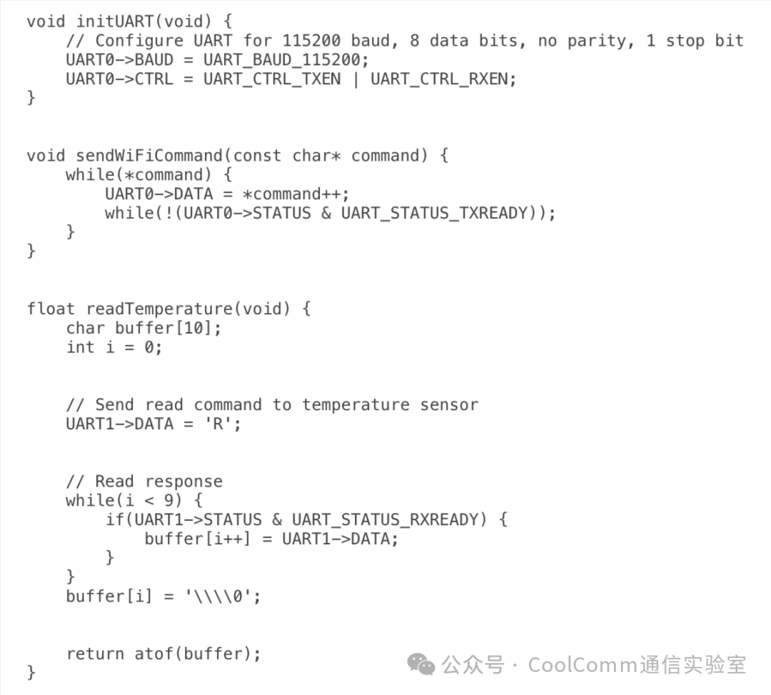
This case study demonstrates how the simplicity and flexibility of UART make it an ideal choice for various components in a smart home thermostat system, enabling effective communication with local sensors and network interfaces.
Implementation Challenges and Solutions
UART Implementation Obstacles
Implementing UART in embedded systems often encounters several challenges that can affect the reliability and efficiency of communication. The most common obstacles are baud rate mismatches and frame errors.
Baud rate mismatch occurs when the transmitter and receiver are not synchronized to the same communication speed. This can lead to data corruption or complete communication failure. To mitigate this issue:
- 1. Use crystal oscillators for precise clock generation.
- 2. Implement automatic baud rate detection algorithms.
- 3. Use standard baud rates (e.g., 9600, 115200) to reduce the likelihood of configuration errors.
Frame errors occur when the receiver detects an invalid stop bit, usually due to noise or synchronization issues. To address frame errors:
- 1. Implement robust start bit detection.
- 2. Use error checking mechanisms, such as parity bits or checksums.
- 3. Adopt software-based frame synchronization techniques.
Other common challenges include buffer overflow, noise interference, and clock drift. To overcome these:
- 1. Implement interrupt-based or DMA-based UART handling to prevent buffer overflow.
- 2. Use appropriate line termination and shielding to reduce noise.
- 3. Periodically resynchronize long data streams to combat clock drift.
SPI Implementation Obstacles
Implementing SPI in embedded systems presents several challenges that can affect communication reliability and system performance. Two major obstacles are clock skew and multi-slave management.
Clock skew occurs when the clock signal arrives at different components at different times due to varying trace lengths or parasitic capacitance. This can lead to data misalignment and communication errors, especially at higher frequencies. To mitigate clock skew:
- 1. Implement proper PCB layout techniques, such as matching the lengths of clock and data lines.
- 2. Use lower clock frequencies for long traces, or consider using differential signaling for high-speed, long-distance communication.
- 3. Use programmable delay lines to fine-tune signal timing.
Managing multiple slaves in an SPI system can be complex, especially when dealing with devices that have different timing requirements or communication protocols. Challenges include:
- 1. Effective slave selection and deselection
- 2. Handling slaves with different SPI modes or clock frequencies
- 3. Ensuring correct timing between slave selection assertion and data transmission
To address these multi-slave management issues:
- 1. Implement flexible slave selection control mechanisms in software.
- 2. Use separate SPI configuration settings for each slave device.
- 3. Adopt a state machine approach to manage different slave protocols.
Other common SPI implementation challenges include:
- 1. Data corruption due to noise or interference
- 2. Efficient handling of full-duplex communication
- 3. Managing SPI bus contention in multi-master systems
To overcome these challenges:
- 1. Use appropriate shielding and grounding techniques to reduce noise.
- 2. Implement DMA for efficient data transfer in full-duplex mode.
- 3. Adopt bus arbitration mechanisms in multi-master configurations.
Pros and Cons of UART vs. SPI
| Parameter | SPI | UART |
| Data Rate | High data rates, typically up to 50 Mbps or higher, suitable for high-speed applications. | Simple implementation, data rates typically up to 1 Mbps, suitable for many use cases. |
| Communication Mode | Full-duplex communication allows simultaneous sending and receiving of data. | Asynchronous communication does not require a clock signal, simplifying wiring. |
| Multiple Devices | Easily communicates with multiple devices using separate slave select (SS) lines. | Suitable for simple point-to-point communication between two devices, standardized and widely supported. |
| Protocol Simplicity | No start/stop bits or parity checks, resulting in lower overhead and faster data transmission. | Built-in error detection mechanisms, such as parity bits, ensure higher data integrity in noisy environments. |
| Data Frame Flexibility | Offers flexible data frame sizes that can be customized based on specific needs. | Supports various baud rates, making it suitable for different applications. |
| Pin Count | Requires more pins (MOSI, MISO, SCLK, SS), which may be a limitation in pin-constrained systems. | Requires fewer pins (only TX and RX), making it suitable for simple or space-constrained designs. |
| Error Checking | No built-in error checking mechanism, requiring additional software for error detection. | Includes error detection mechanisms, such as parity bits, enhancing reliability. |
| Communication Distance | More suitable for short-distance communication due to potential signal degradation. | More suitable for long-distance communication as it is more resilient to signal degradation. |
| System Complexity | Managing multiple slaves can be complex, especially when additional SS lines are required. | Limited to point-to-point communication, making it less suitable for complex multi-device systems. |
| Communication Mode | Synchronous characteristics require a clock signal, increasing design complexity. | Half-duplex communication means data can only be sent or received at a time on the same line. |
Conclusion
UART and SPI are fundamental communication protocols in embedded systems, each with its unique characteristics. UART offers simplicity and long-distance communication with minimal pin usage, while SPI provides high-speed, synchronous data transmission and support for multiple slave devices. The asynchronous nature of UART allows for flexible timing but may be affected by synchronization issues, while SPI’s synchronous design ensures precise timing but requires more signal lines.
When choosing between UART and SPI, it is important to consider factors such as data rate requirements, the number of devices, and the distance between devices.
Understanding these two protocols is crucial for effective embedded system design. Each protocol has its place in the embedded ecosystem, and proficiency in both allows engineers to make informed decisions based on specific project requirements. When selecting a protocol, carefully evaluate factors such as speed, complexity, power consumption, and specific application needs. The right choice can significantly impact system performance, cost, and development time.
Frequently Asked Questions
- 1. Can UART and SPI be used in the same system?
Yes, many embedded systems use both UART and SPI simultaneously for different purposes. For example, UART may be used for debugging communication, while SPI is used for interfacing with sensors or storage devices.
- 2. How can I convert between UART and SPI protocols?
Protocol conversion can be achieved using a microcontroller as a bridge or by using dedicated protocol converter ICs. The microcontroller receives data from one protocol and retransmits it using another.
- 3. Are there modern alternatives to UART and SPI?
Yes, protocols such as I2C, CAN, and USART provide alternatives with different characteristics. For high-speed applications, RS-485 based on UART or Quad-SPI derived from SPI are also used.
- 4. How do UART and SPI compare in terms of power consumption?
Generally, SPI consumes more power due to its higher clock speeds and multiple signal lines. UART can be more energy-efficient at lower baud rates, making it suitable for battery-powered devices.
- 5. Can UART or SPI be used for wireless communication?
While UART and SPI are primarily wired protocols, they can interface with wireless modules. For example, UART is commonly used to communicate with Bluetooth or Wi-Fi modules, which then handle wireless transmission.
- 6. How do I handle communication between devices with different voltage levels using UART or SPI?
Level shifters or voltage converters can be used to safely interface between devices with different voltage levels. Some modern ICs also have built-in level shifting capabilities.
- 7. What are the implications of using UART or SPI in real-time systems?
SPI’s deterministic timing makes it very suitable for real-time systems. UART can be used in real-time systems but may require careful timing considerations and potentially higher baud rates to meet strict timing requirements.
Tap to view and share quality information with friends..
Ten thousand reads – a collection of the most popular articles
The development of communication and fundamental issues – a must-read for communication professionals!
The top ten events in the communication field in 2024
From electromagnetic waves to I/Q signals: Understanding I/Q sampling in 10 minutes (Part 1)
Classification of communication systems in communication principles
From MATLAB to FPGA: How communication algorithms are implemented?
Paid collection of communication system simulation methodologies (completed)
Practical digital signal processing series content compilation (completed)
Introduction to PLL principles: Six methods to achieve synchronization
The arrival of the Starlink V3 era – the despairing upgrade speed that we find hard to keep up with?
Introduction to MIMO (Part 1)
Two birds with one stone: I/Q signals and Fourier transforms (Part 1)
Pulse radar – the power of pulse compression
See more valuable articles
Please long press the image below
Scan the QR code to follow coolcomm