 Editor
SPI (Serial Peripheral Interface) is a high-speed full-duplex synchronous serial communication interface developed by Motorola, widely used for communication between microcontrollers and various peripherals (such as Flash, sensors, ADCs, etc.). This article will introduce the working principle of SPI and demonstrate how to use the SPI interface through practical code examples from the STM32 standard library.
1. What is SPI? – A Simple Explanation
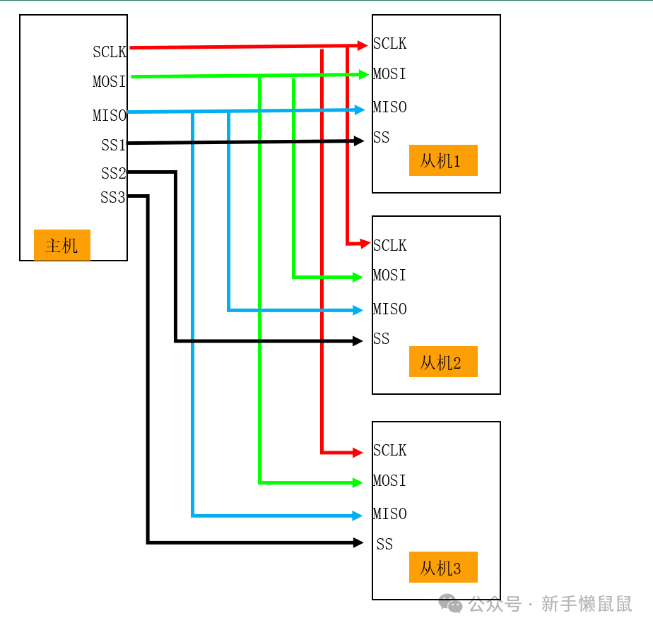
SPI is like an efficient courier system, consisting of four key components:
- SCK (Clock Line): Equivalent to the schedule of the courier vehicle, indicating when both parties should send/receive data.
- MOSI (Master Out Slave In): A dedicated channel for the master device (like STM32) to send data, similar to the conveyor belt of a warehouse.
- MISO (Master In Slave Out): A dedicated channel for the master device to receive data, akin to the conveyor belt for incoming goods.
- NSS/CS (Chip Select Line): Similar to the access control of a warehouse, only the selected device can participate in communication.
The biggest feature of SPI is full-duplex synchronous communication, which means data can be transmitted in both directions simultaneously, like a two-way street without interference.
Its transmission speed is usually much faster than I2C, reaching several Mbps.
 Editor
2. Working Principle of SPI – An In-Depth Explanation
1. Master-Slave Mode
SPI adopts a master-slave architecture, similar to the relationship between a teacher and students:
- Master Device (Teacher): Controls the clock signal, determining when to start and end communication.
- Slave Device (Student): Responds to the master device’s commands and only participates in communication when selected.
A master device can connect to multiple slave devices, but it needs to select them through different chip select lines (CS).
2. Four Operating Modes
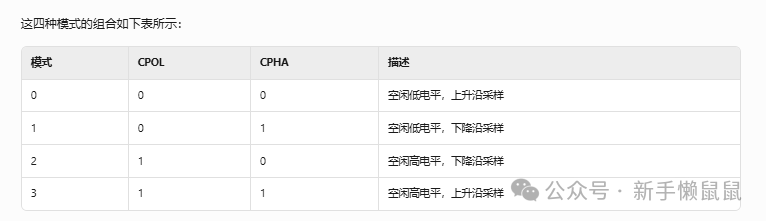
SPI has four operating modes, determined by two parameters:
-
CPOL (Clock Polarity): The state of the clock line when idle.
- 0: Low level when idle.
- 1: High level when idle.
-
CPHA (Clock Phase): The timing of data sampling.
0: Sample on the first clock edge. 1: Sample on the second clock edge.
 Editor Phase Supplement Knowledge Point
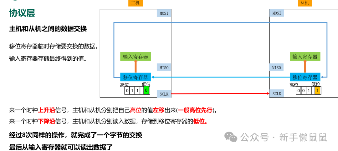
Data transmission in SPI is like passing a note in a relay:
- The master device pulls down the corresponding slave device’s CS line to select it.
- The master device provides the clock signal through SCK.
- The master device sends data through MOSI while receiving data through MISO.
- Data is transmitted one bit at a time in the form of a shift register, usually with the most significant bit (MSB) first.
- After transmission is complete, the master device pulls the CS line high to end communication.
 Editor
3. Practical SPI Configuration with STM32 Standard Library
Next, we will detail how to configure and use the SPI interface through code examples from the STM32 standard library.
1. SPI Initialization Configuration
First, we need to initialize the SPI interface and the related GPIO pins:
#include "stm32f10x.h"

// Define SPI and GPIO ports and pins
#define SPIx SPI1
#define SPIx_CLK_ENABLE() RCC_APB2PeriphClockCmd(RCC_APB2Periph_SPI1, ENABLE)
#define SPIx_GPIO_PORT GPIOA
#define SPIx_SCK_PIN GPIO_Pin_5
#define SPIx_MISO_PIN GPIO_Pin_6
#define SPIx_MOSI_PIN GPIO_Pin_7
#define NSS_GPIO_PORT GPIOB
#define NSS_PIN GPIO_Pin_0

// SPI configuration structure
SPI_InitTypeDef SPI_InitStructure;

void SPI1_Init(void) {
    // 1. Enable clock
    SPIx_CLK_ENABLE(); // Enable SPI1 clock
    RCC_APB2PeriphClockCmd(RCC_APB2Periph_GPIOA | RCC_APB2Periph_GPIOB, ENABLE);

    // 2. Configure GPIO pins
    GPIO_InitTypeDef GPIO_InitStructure;

    // Configure SCK, MOSI as alternate push-pull output
    GPIO_InitStructure.GPIO_Pin = SPIx_SCK_PIN | SPIx_MOSI_PIN;
    GPIO_InitStructure.GPIO_Mode = GPIO_Mode_AF_PP; // Alternate push-pull output
    GPIO_InitStructure.GPIO_Speed = GPIO_Speed_50MHz;
    GPIO_Init(SPIx_GPIO_PORT, &GPIO_InitStructure);

    // Configure MISO as floating input
    GPIO_InitStructure.GPIO_Pin = SPIx_MISO_PIN;
    GPIO_InitStructure.GPIO_Mode = GPIO_Mode_IN_FLOATING;
    GPIO_Init(SPIx_GPIO_PORT, &GPIO_InitStructure);

    // Configure NSS as normal push-pull output (software control)
    GPIO_InitStructure.GPIO_Pin = NSS_PIN;
    GPIO_InitStructure.GPIO_Mode = GPIO_Mode_Out_PP;
    GPIO_Init(NSS_GPIO_PORT, &GPIO_InitStructure);
    GPIO_SetBits(NSS_GPIO_PORT, NSS_PIN); // Initial state not selected

    // 3. Initialize SPI parameters
    SPI_InitStructure.SPI_Direction = SPI_Direction_2Lines_FullDuplex; // Two-line full duplex
    SPI_InitStructure.SPI_Mode = SPI_Mode_Master; // Master mode
    SPI_InitStructure.SPI_DataSize = SPI_DataSize_8b; // 8-bit data
    SPI_InitStructure.SPI_CPOL = SPI_CPOL_Low; // Clock polarity: idle low
    SPI_InitStructure.SPI_CPHA = SPI_CPHA_1Edge; // Clock phase: sample on first edge
    SPI_InitStructure.SPI_NSS = SPI_NSS_Soft; // Software control NSS
    SPI_InitStructure.SPI_BaudRatePrescaler = SPI_BaudRatePrescaler_16; // Baud rate prescaler
    SPI_InitStructure.SPI_FirstBit = SPI_FirstBit_MSB; // MSB first
    SPI_Init(SPIx, &SPI_InitStructure);

    // 4. Enable SPI
    SPI_Cmd(SPIx, ENABLE);
}
2. SPI Data Sending Function
Below is the implementation of the function for the master device to send data:
void SPI_Master_Send(uint8_t* pData, uint16_t Size) {
    // 1. Pull down NSS, select the slave device
    GPIO_ResetBits(NSS_GPIO_PORT, NSS_PIN);

    // 2. Loop to send data
    while (Size--) {
        // Wait for the transmit buffer to be empty
        while (SPI_I2S_GetFlagStatus(SPIx, SPI_I2S_FLAG_TXE) == RESET);

        // Send data
        SPI_I2S_SendData(SPIx, *pData++);
    }

    // 3. Wait for transmission to complete
    while (SPI_I2S_GetFlagStatus(SPIx, SPI_I2S_FLAG_BSY) == SET);

    // 4. Pull up NSS, release the slave device
    GPIO_SetBits(NSS_GPIO_PORT, NSS_PIN);
}
3. SPI Data Receiving Function
SPI is full-duplex, meaning it receives data while sending. Below is the implementation for receiving data:
uint8_t SPI_ReceiveByte(void) {
    // Send dummy data (0xFF) to generate clock signal
    SPI_I2S_SendData(SPIx, 0xFF);

    // Wait for the receive buffer to be non-empty
    while (SPI_I2S_GetFlagStatus(SPIx, SPI_I2S_FLAG_RXNE) == RESET);

    // Return the received data
    return SPI_I2S_ReceiveData(SPIx);
}

void SPI_Master_Receive(uint8_t* pData, uint16_t Size) {
    // 1. Pull down NSS, select the slave device
    GPIO_ResetBits(NSS_GPIO_PORT, NSS_PIN);

    // 2. Loop to receive data
    while (Size--) {
        *pData++ = SPI_ReceiveByte();
    }

    // 3. Pull up NSS, release the slave device
    GPIO_SetBits(NSS_GPIO_PORT, NSS_PIN);
}
4. Example of Main Function
Below is a complete example of the main function demonstrating how to send and receive data:
int main(void) {
    // 1. Initialize system clock, etc.
    SystemInit();

    // 2. Initialize SPI
    SPI1_Init();

    // 3. Prepare data to send
    uint8_t txData[] = {0x01, 0x02, 0x03, 0x04};
    uint8_t rxData[4];

    while (1) {
        // 4. Send data
        SPI_Master_Send(txData, sizeof(txData));

        // 5. Receive data
        SPI_Master_Receive(rxData, sizeof(rxData));

        // 6. Simple delay
        for (volatile uint32_t i = 0; i < 1000000; i++);
    }
}
4. Common Issues and Solutions in SPI Usage
When using SPI in practice, various issues may arise. Below are some common problems and their solutions:
-
Data Transmission Errors
- Possible Cause: CPOL and CPHA settings do not match the slave device.
- Solution: Check the slave device manual to ensure the mode settings of the master and slave devices are consistent.
No Response in Communication
- Possible Cause: Chip select signal (NSS) is not controlled correctly.
- Solution: Use a logic analyzer to check the NSS signal, ensuring it remains low during communication.
Unstable Data Rate
- Possible Cause: Baud rate prescaler is set incorrectly.
- Solution: Lower the baud rate or check the clock configuration.
Multiple Slave Device Conflicts
- Possible Cause: Multiple slave devices’ chip select lines are activated simultaneously.
- Solution: Ensure that only one slave device is selected at a time.
Long-Distance Communication Issues
- Possible Cause: SPI is designed for short-distance communication, and long distances can lead to signal attenuation.
- Solution: Add driver circuits or switch to other communication protocols like RS485.
5. Comparison of SPI with Other Communication Protocols
To better understand the characteristics of SPI, we will compare it with common I2C and UART protocols:
| Feature | SPI | I2C | UART |
|---|---|---|---|
| Communication Method | Synchronous Full-Duplex | Synchronous Half-Duplex | Asynchronous Full-Duplex |
| Number of Wires | 4 Wires (at least 3 wires) | 2 Wires | 2 Wires (excluding ground) |
| Maximum Rate | Several Mbps | 400Kbps-3.4Mbps | Typically <1Mbps |
| Addressing Method | Hardware Chip Select | Software Address | Point-to-Point |
| Complexity | Medium | Low | Low |
| Applicable Scenarios | High-Speed Peripherals | Medium-Low Speed Peripherals | Device-to-Device Communication |
From the comparison, it can be seen that SPI has advantages in speed and full-duplex, but is slightly inferior to I2C in terms of multi-device support and line complexity.
6. Advanced SPI Application Techniques
For applications requiring higher performance or more complex functions, consider the following advanced techniques:
Using DMA for Transmission
Advantages: Reduces CPU overhead and improves transmission efficiency.Implementation: Configure SPI and DMA controllers for automatic data transfer.
Interrupt-Driven Communication
- Advantages: Improves system responsiveness.
- Implementation: Enable SPI interrupts and handle data in the interrupt service routine.
Hardware NSS Management
- Advantages: More precise chip select control.
- Implementation: Configure SPI_InitStructure.SPI_NSS = SPI_NSS_Hard.
16-Bit Data Mode
Advantages: Improves transmission efficiency (suitable for 16-bit peripherals).Implementation: Set SPI_InitStructure.SPI_DataSize = SPI_DataSize_16b;
7. Conclusion
SPI is an efficient and flexible serial communication interface, particularly suitable for high-speed data exchange between STM32 and various peripherals. Through this article, you should have mastered:
1. The basic working principles and characteristics of SPI.2. The SPI configuration method using the STM32 standard library.3. Complete code implementation for SPI sending and receiving.4. Common issues and solutions in SPI usage.5. Comparison of SPI with other communication protocols.6. Advanced SPI application techniques.
In practical projects, it is recommended to adjust SPI parameters according to the specific requirements of peripherals and fully utilize the hardware features of STM32 (such as DMA) to optimize performance. Additionally, using tools like logic analyzers to debug SPI communication can greatly enhance development efficiency.